(Solved): An inverting amplifier is shown in schematic 2. In this amplifier, the output voltage is the opposit ...
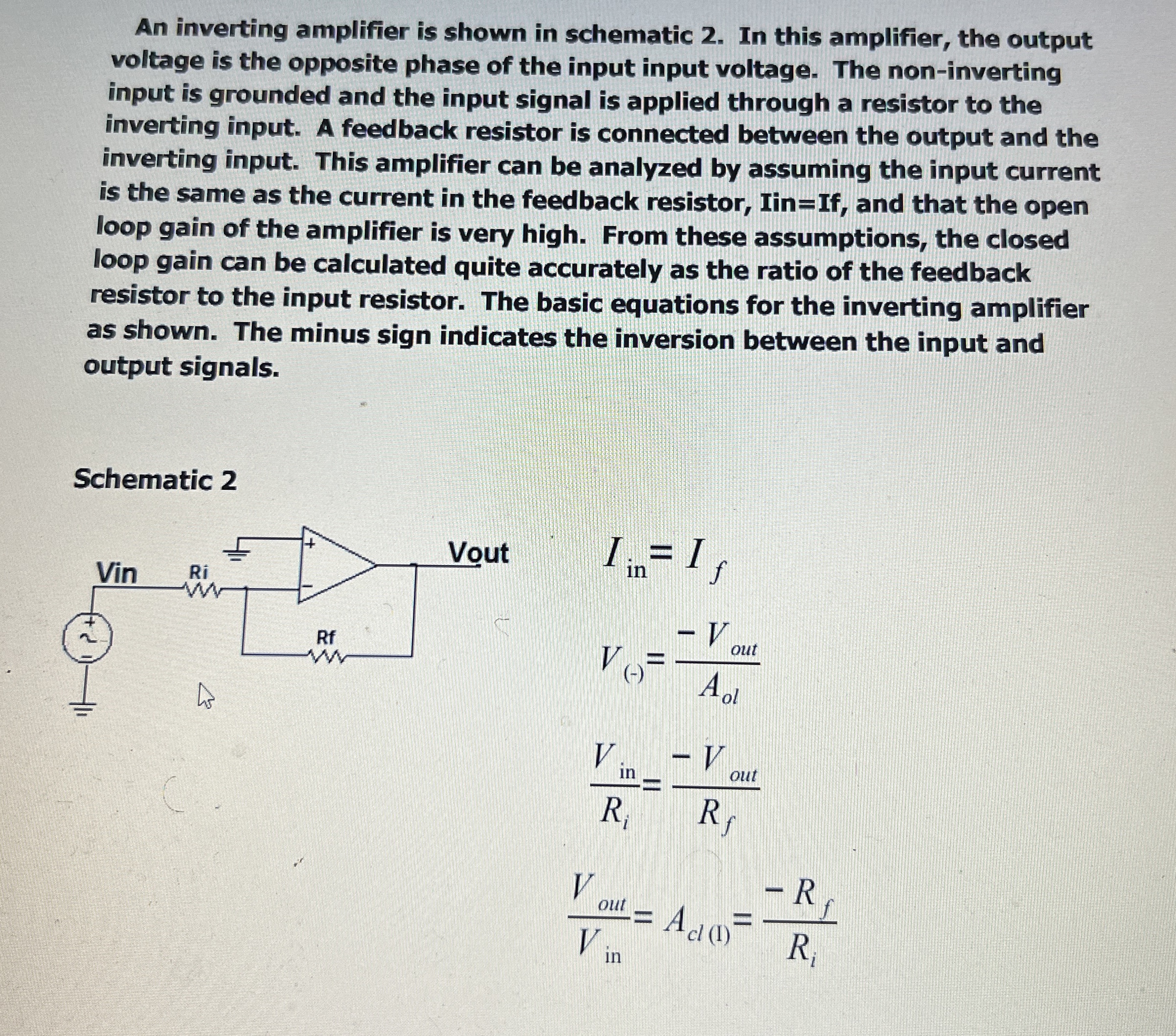
An inverting amplifier is shown in schematic 2. In this amplifier, the output voltage is the opposite phase of the input input voltage. The non-inverting input is grounded and the input signal is applied through a resistor to the inverting input. A feedback resistor is connected between the output and the inverting input. This amplifier can be analyzed by assuming the input current is the same as the current in the feedback resistor, Iin=If, and that the open loop gain of the amplifier is very high. From these assumptions, the closed loop gain can be calculated quite accurately as the ratio of the feedback resistor to the input resistor. The basic equations for the inverting amplifier as shown. The minus sign indicates the inversion between the input and output signals. Schematic 2
I_(in)=I_(f)
V_((-))=(-V_(out))/(A_(ol))
(V_(in))/(R_(i))=(-V_(out))/(R_(f))
(V_(out))/(V_(in))=A_(cl(I))=(-R_(f))/(R_(i))