Home /
Expert Answers /
Electrical Engineering /
figure-q6-a-shows-a-power-mosfet-switched-from-a-control-circuit-and-driving-a-dc-load-a-explai-pa498
(Solved): Figure Q6(a) shows a power MOSFET switched from a control circuit and driving a dc load. (a) Explai ...
Figure Q6(a) shows a power MOSFET switched from a control circuit and driving a dc load. (a) Explain why the gate drive output signal cannot share the same ground as the
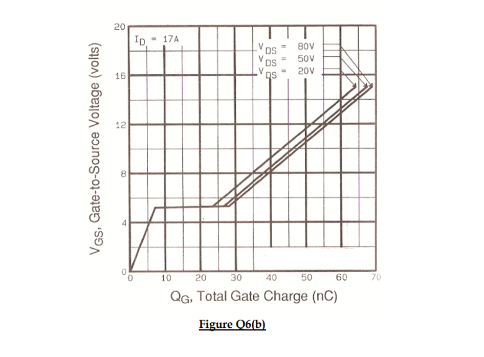
50Vsupply. [3 marks] (b) With the help of a diagram, outline one method for implementing the isolation stage. [5 marks] (c) The power MOSFET has a gate threshold voltage of
3.0V. Its corresponding gate charge curve is shown in Figure Q6(b). The device has a switching frequency of
4kHzand is required to turn on within
200ns. (i) Calculate the current sourcing capability of the gate drive, and the value of the gate resistance.
[3+3 marks ](ii) Estimate the current rise time and voltage fall time, if the current calculated in Part (c)(i) is applied to the gate.
[3+3 marks ]F1gure Uo(D)