Home /
Expert Answers /
Electrical Engineering /
the-figure-below-shows-the-simulation-output-of-a-dc-motor-drive-system-obtained-from-a-matlab-simul-pa382
(Solved): The figure below shows the simulation output of a DC motor drive system obtained from a MATLAB/Simul ...
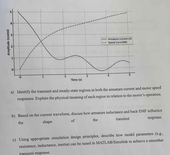
The figure below shows the simulation output of a DC motor drive system obtained from a MATLAB/Simulink model. The graph represents both armature current (A) and motor speed (rpm) as functions of time. a) Identify the transient and steady-state regions in both the armature current and motor speed responses. Explain the physical meaning of each region in relation to the motor's operation. b) Based on the current waveform, discuss how armature inductance and back EMF influence the shape of the transient response. c) Using appropriate simulation design principles, describe how model parameters (e.g., resistance, inductance, inertia) can be tuned in MATLAB/Simulink to achieve a smoother transient response.