Home /
Expert Answers /
Electrical Engineering /
1-6-the-zbus-matrix-of-the-power-system-shown-is-figure-2-is-j-0-0295-0-0178-0-0256-0-0178-0-023-pa571
(Solved): 1.6 The Zbus Matrix of the power system shown is figure 2 is: j[[0.0295,0.0178,0.0256],[0.0178,0.023 ...
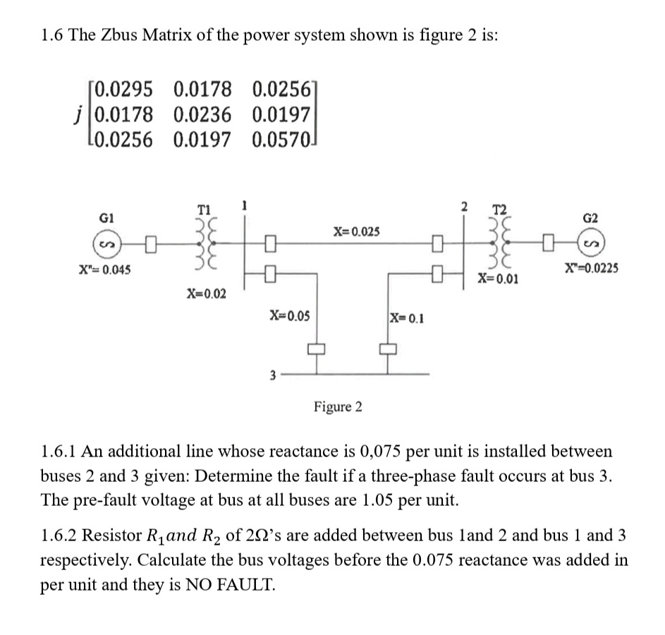
1.6 The Zbus Matrix of the power system shown is figure 2 is:
j[[0.0295,0.0178,0.0256],[0.0178,0.0236,0.0197],[0.0256,0.0197,0.0570]]1.6.1 An additional line whose reactance is 0,075 per unit is installed between buses 2 and 3 given: Determine the fault if a three-phase fault occurs at bus 3. The pre-fault voltage at bus at all buses are 1.05 per unit. 1.6.2 Resistor
R_(1)and
R_(2)of
2\Omega 's are added between bus 1 and 2 and bus 1 and 3 respectively. Calculate the bus voltages before the 0.075 reactance was added in per unit and they is NO FAULT.