(Solved): 1. Determine the input-output transfer function model \( H(s)=V_{R 4}(s) / V_{1}(s) \) for the elect ...
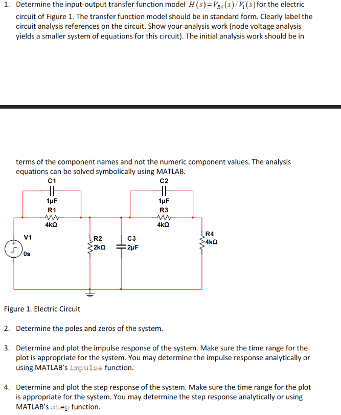
1. Determine the input-output transfer function model \( H(s)=V_{R 4}(s) / V_{1}(s) \) for the electric circuit of Figure 1. The transfer function model should be in standard form. Clearly label the circuit analysis references on the circuit. Show your analysis work (node voltage analysis yields a smaller system of equations for this circuit). The initial analysis work should be in terms of the component names and not the numeric component values. The analysis equations can be solved symbolically using MATLAB. Figure 1. Electric Circuit 2. Determine the poles and zeros of the system. 3. Determine and plot the impulse response of the system. Make sure the time range for the plot is appropriate for the system. You may determine the impulse response analytically or using MATLAB's impul se function. 4. Determine and plot the step response of the system. Make sure the time range for the plot is appropriate for the system. You may determine the step response analytically or using MATLAB's step function.