(Solved): 1 Exercise The schematic of a shaft is illustrated in the figure below. The shaft is supported by t ...
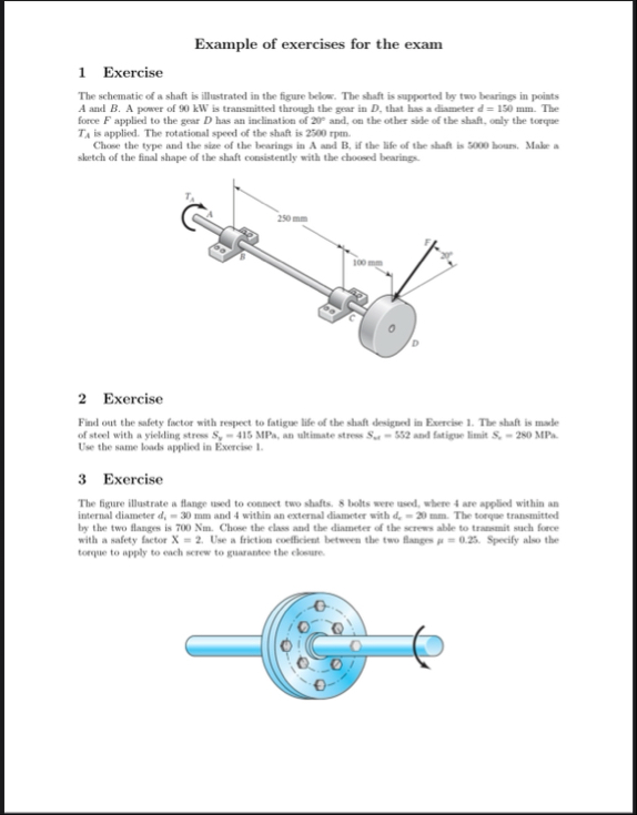
1 Exercise The schematic of a shaft is illustrated in the figure below. The shaft is supported by two bearings in points
Aand
B. A power of 90 kW is transmitted through the gear in
D, that has a diameter
d=150mm. The force
Fapplied to the gear
Dhas an inclination of
20\deg and, on the other side of the shaft, only the torque
T_(A)is applied. The rotational speed of the shaft is 2500 rpm . Chose the type and the size of the bearings in A and B, if the life of the shaft is 5000 hours. Make a sketch of the final shape of the shaft consistently with the choosed bearings. 2 Exercise Find out the safety factor with respect to fatigue life of the shaft designed in Exercise 1. The shaft is made of steel with a yielding stress
S_(y)=415MPa, an ultimate stress
S_(at )=552and fatigue limit
S,=280MPa. Use the same loads applied in Exercise 1. 3 Exercise The figure illustrate a flange used to consect two shafts. 8 bolts were used, where 4 are applied within an internal diameter
d_(i)=30mmand 4 within an external diameter with
d_(c)=30mm. The torque transmitted by the two flanges is 700 Nm . Chose the class and the diameter of the screws able to transmit such force with a safety factor
x=2. Use a friction coefficiest between the two flanges
p=0.25. Specify also the torque to apply to each screw to guarantee the closure.