Home /
Expert Answers /
Electrical Engineering /
3-use-multisim-to-build-the-4-bit-full-adder-circuit-shown-below-in-figure-5-include-the-schemati-pa591
(Solved): 3. Use Multisim to build the 4-bit full adder circuit shown below in Figure 5. Include the schemati ...

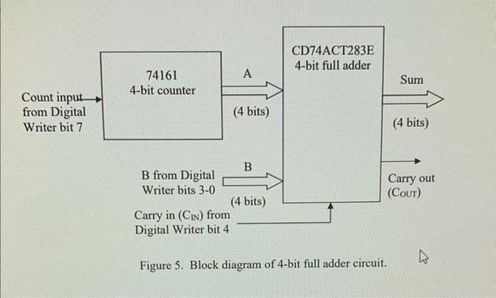
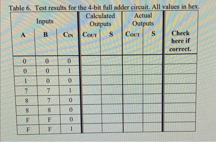
3. Use Multisim to build the 4-bit full adder circuit shown below in Figure 5. Include the schematic in your Pre-lab. Fill in a table of results similar to Table 6. Are your results correct?
Figure 5. Block diagram of 4-bit full adder circuit.
Tahlo 6 Test reculte for the 4 -hit full adder circuit. All values in heX.