Home / Expert Answers / Electrical Engineering / 4-please-interpret-and-explain-the-following-ladder-logic-diagrams-and-answer-the-questions-in-d-pa900

(Solved): 4). Please interpret and explain the following ladder logic diagrams and answer the questions in d ...


4). Please interpret and explain the following ladder logic diagrams and answer the questions in detail
A. When is output LT1

4). Please interpret and explain the following ladder logic diagrams and answer the questions in detail A. When is output LT17 ON? B. When is output LT16 ON?


We have an Answer from Expert

View Expert Answer

Expert Answer


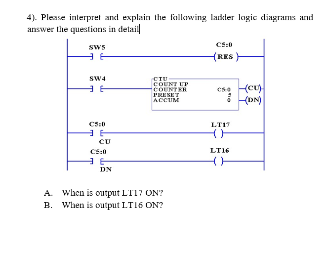
In the given programmable logic control (PLC) ladder diagram, we have 2 input contact switch, 1 up counter, 2 output coil and 1 reset coil.
We have an Answer from Expert

Buy This Answer $5

Place Order

We Provide Services Across The Globe