Home /
Expert Answers /
Electrical Engineering /
5-a-consider-the-circuit-shown-in-the-figure-below-first-find-a-differential-equation-model-for-pa610
(Solved): *5. a) Consider the circuit shown in the Figure below. First find a differential equation model for ...
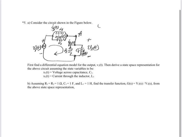
*5. a) Consider the circuit shown in the Figure below. First find a differential equation model for the output, . Then derive a state space representation for the above circuit assuming the state variables to be: Voltage across capacitance, . Current through the inductor, b) Assuming , and , find the transfer function, , from the above state space representation,