Home /
Expert Answers /
Electrical Engineering /
7-using-figure-6-doint-for-the-circuit-in-figure-5-assume-dc-200-8-using-figure-6-d-pa288
(Solved): 7. Using Figure 6 - Doint for the circuit in Figure 5. Assume dc=200. 8. Using Figure 6, D ...
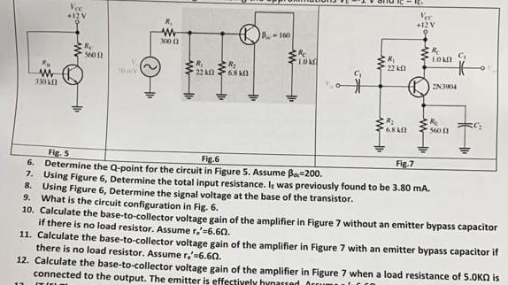
7. Using Figure 6 - Doint for the circuit in Figure 5. Assume . 8. Using Figure 6, Determine the total input resistance. It was previously found to be . 9. What is the 6 , Determine the signal voltage at the base of the transistor. 10. Calculate circuit configuration in Fig. 6 . if there is the base-to-collector voltage gain of the amplifier in Figure 7 without an emitter bypass capacitor 11. Caleulate the bad resistor. Assume . there is the base-to-collector voltage gain of the amplifier in Figure 7 with an emitter bypass capacitor if 12. Calculate is no load resistor. Assume . Calculate the base-to-collector voltage gain of the amplifier in Figure 7 when a load resistance of is
Expert Answer
Solution Given the BJT circuit, 6] So the value of the Q-point will be So the collector current wi...