(Solved): A general fourbar linkage configuration and its notation are shown in Figure P6-1. The \table[[TA ...
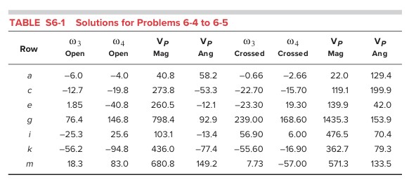
A general fourbar linkage configuration and its notation are shown in Figure P6-1. The \table[[TABLE S6-1,Solutions for Problems 6-4 to 6-5],[Row,\table[[\omega _(3)],[Open]],\table[[\omega _(4)],[Open]],\table[[V_(P)],[Mag]],\table[[V_(P)],[Ang]],\table[[\omega _(3)],[Crossed]],\table[[\omega _(4)],[Crossed]],\table[[V_(P)],[Mag]],\table[[V_(P)],[Ang]],],[-6.0,-4.0,40.8,58.2,-0.66,-2.66,22.0,129.4,],[c,-12.7,-19.8,273.8,-53.3,-22.70,-15.70,119.1,199.9,],[e,1.85,-40.8,260.5,-12.1,-23.30,19.30,139.9,42.0,],[g,76.4,146.8,798.4,92.9,239.00,168.60,1435.3,153.9,],[i,-25.3,25.6,103.1,-13.4,56.90,6.00,476.5,70.4,],[k,-56.2,-94.8,436.0,-77.4,-55.60,-16.90,362.7,79.3,],[m,18.3,83.0,680.8,149.2,7.73,-57.00,571.3,133.5,]] link lengths, coupler point location, and the values of \theta 2 and \omega 2 for the same fourbar linkages as used for position analysis in Chapter 4 are redefined in Table P6-1, which is basically the same as Table P4-1. For the row(s) assigned, draw the linkage to scale and find the velocities of the pin joints A and B and of instant centers I1,3 and I2,4 using a graphical method. Then calculate \omega 3 and \omega 4 and find the velocity of point P. Use graphical vector polygon, open configuration only. I have also attached the answers for ROW C. Please do ROW C please! TABLE P6-1 Data for Problems 6-4 to 6-5 *