Home /
Expert Answers /
Electrical Engineering /
a-gray-code-is-a-way-of-encoding-binary-numbers-so-that-only-one-digit-changes-from-one-number-to-pa285
(Solved): A Gray code is a way of encoding binary numbers so that only one digit changes from one number to ...


A Gray code is a way of encoding binary numbers so that only one digit changes from one number to the next. To construct the code there are two simple rules. First start with all 0 s and then proceed by changing the least significant bit (LSB) which will bring about a new state. That means that a single 0 can change to a 1 , or a single 1 can change to a zero: Table 2. The Binary code and the corresponding Gray code Gray coding is an important code and is used for its speed, it is also relatively free from errors. In pure binary coding counting from 7 (0111) to 8 (1000) requires 4 bits to be changed simultaneously. If this does not happen then various numbers could be momentarily generated during the transition, so this creates spurious numbers which could be read. Gray coding avoids this since only one bit changes between subsequent numbers.
A Gray code is a way of encoding binary numbers so that only one digit changes from one number to the next. To construct the code there are two simple rules. First start with all 0 s and then proceed by changing the least significant bit (LSB) which will bring about a new state. That means that a single 0 can change to a 1 , or a single 1 can change to a zero: Table 2. The Binary code and the corresponding Gray code Gray coding is an important code and is used for its speed, it is also relatively free from errors. In pure binary coding counting from 7 (0111) to 8 (1000) requires 4 bits to be changed simultaneously. If this does not happen then various numbers could be momentarily generated during the transition, so this creates spurious numbers which could be read. Gray coding avoids this since only one bit changes between subsequent numbers.
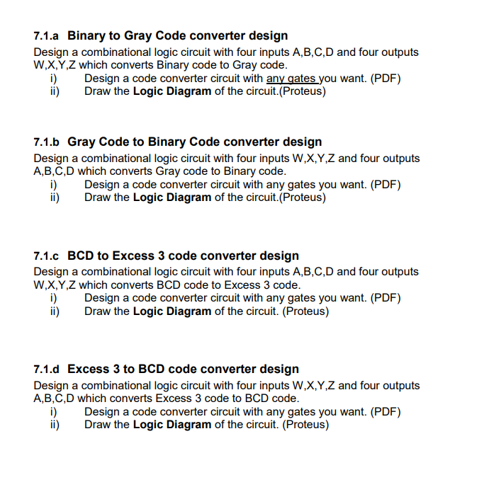
7.1.a Binary to Gray Code converter design Design a combinational logic circuit with four inputs A,B,C,D and four outputs which converts Binary code to Gray code. i) Design a code converter circuit with any gates you want. (PDF) ii) Draw the Logic Diagram of the circuit.(Proteus) 7.1.b Gray Code to Binary Code converter design Design a combinational logic circuit with four inputs and four outputs which converts Gray code to Binary code. i) Design a code converter circuit with any gates you want. (PDF) ii) Draw the Logic Diagram of the circuit.(Proteus) 7.1.c to Excess 3 code converter design Design a combinational logic circuit with four inputs A,B,C,D and four outputs which converts code to Excess 3 code. i) Design a code converter circuit with any gates you want. (PDF) ii) Draw the Logic Diagram of the circuit. (Proteus) 7.1.d Excess 3 to BCD code converter design Design a combinational logic circuit with four inputs and four outputs A,B,C,D which converts Excess 3 code to code. i) Design a code converter circuit with any gates you want. (PDF) ii) Draw the Logic Diagram of the circuit. (Proteus)