Home /
Expert Answers /
Electrical Engineering /
a-your-classmate-came-up-with-the-following-verilog-code-for-a-2-to-4-decoder-with-enable-however-pa858
(Solved): a. Your classmate came up with the following verilog code for a 2-to-4 decoder with enable. However ...
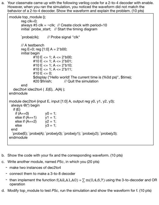
a. Your classmate came up with the following verilog code for a 2-to-4 decoder with enable. However, when you ran the simulation, you noticed the waveform did not match the behavior of a 2 -to-4 decoder. Show the waveform and explain the problem. (10 pts) b. Show the code with your fix and the corresponding waveform. (10 pts) c. Write another module, named \( P 5 c \), in which you ( \( 20 \mathrm{pts}) \) - make two instances of dec2to4 - connect them to make a 3-to-8 decoder - then implement the function \( \mathrm{f}(\mathrm{A} 2, \mathrm{~A} 1, \mathrm{AO})=\sum \mathrm{m}(0,4,6,7) \) using the 3-to-decoder and \( \mathrm{OR} \) operation d. Modify top_module to test P5c, run the simulation and show the waveform for \( \mathrm{f} \). (10 pts)
Expert Answer
Part-a In this part, a verilog description of 2-to-4 decoder is given along with testbench. The simultion waveform for the given code has been obtained and can viewed as follows: The functionality of 2 to 4 decoder with E, A1, A0 as input and Y