Home /
Expert Answers /
Electrical Engineering /
c-the-digital-logic-circuit-in-fig-1-shows-a-simple-alarm-control-circuit-fig-1-h-implement-the-d-pa388
(Solved): c) The digital logic circuit in fig 1 shows a simple alarm control circuit. Fig 1 h) Implement the d ...
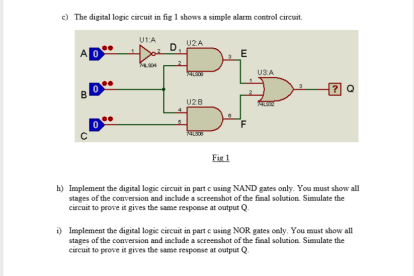
c) The digital logic circuit in fig 1 shows a simple alarm control circuit. Fig 1 h) Implement the digital logic circuit in part
cusing NAND gates only. You must show all stages of the conversion and include a screenshot of the final solution. Simulate the circuit to prove it gives the same response at output
Q. i) Implement the digital logic circuit in part c using NOR gates only. You must show all stages of the conversion and include a screenshot of the final solution. Simulate the circuit to prove it gives the same response at output
Q.