(Solved): Cisco 2950 series switch Figure 12-1 Lab 12.1 configuration Lab 12.1 Configure a Cisco 2950 Switch ...
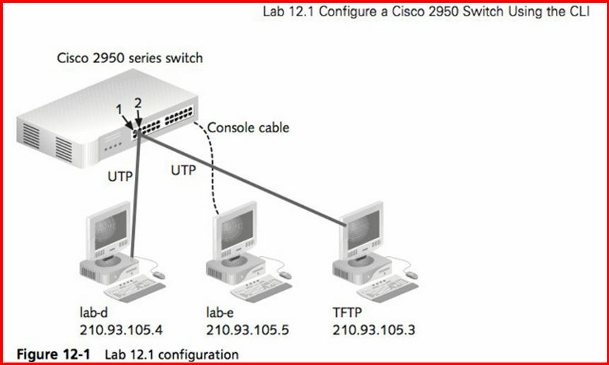
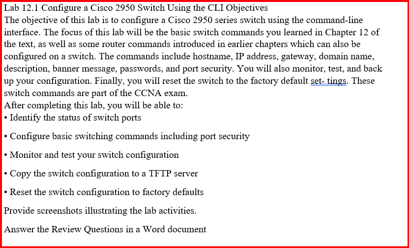
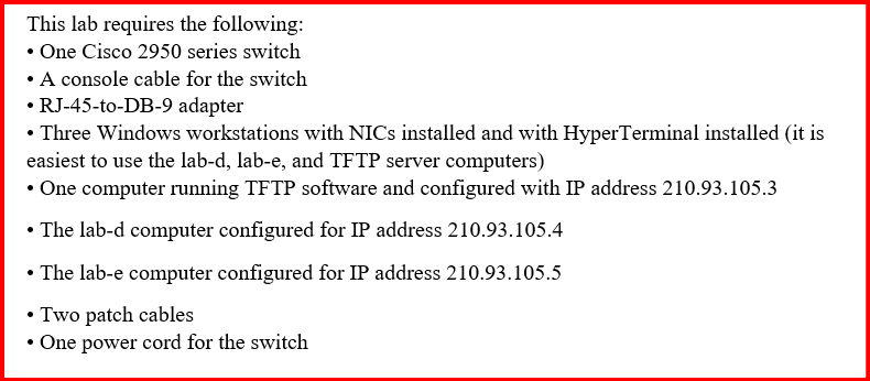
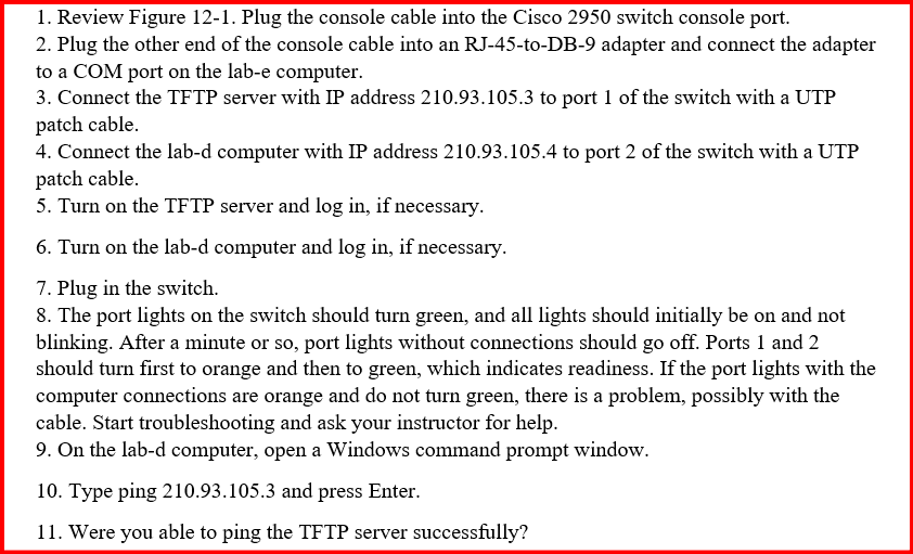
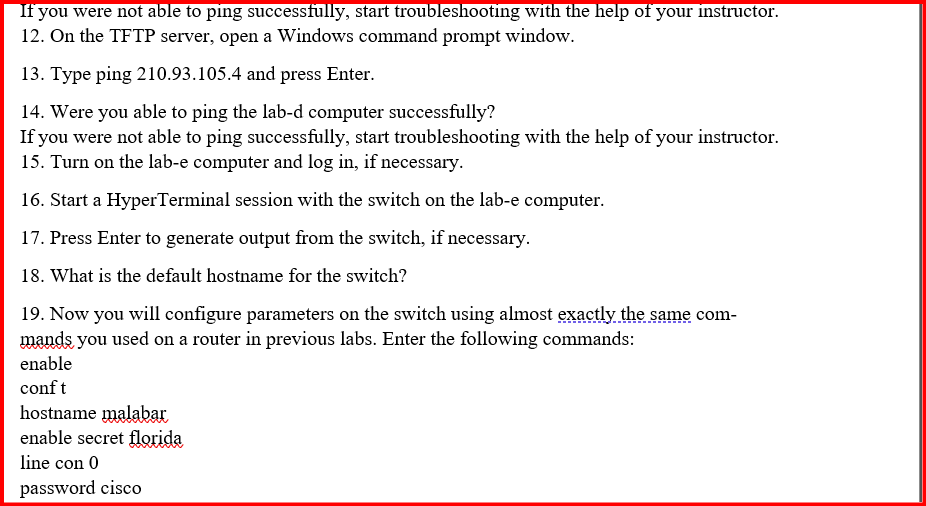
Cisco 2950 series switch Figure 12-1 Lab 12.1 configuration Lab 12.1 Configure a Cisco 2950 Switch Using the CLI Objectives The objective of this lab is to configure a Cisco 2950 series switch using the command-line interface. The focus of this lab will be the basic switch commands you learned in Chapter 12 of the text, as well as some router commands introduced in earlier chapters which can also be configured on a switch. The commands include hostname, IP address, gateway, domain name, description, banner message, passwords, and port security. You will also monitor, test, and back up your configuration. Finally, you will reset the switch to the factory default set-tings. These switch commands are part of the CCNA exam. After completing this lab, you will be able to: Identify the status of switch ports Configure basic switching commands including port security Monitor and test your switch configuration Copy the switch configuration to a TFTP server Reset the switch configuration to factory defaults Provide screenshots illustrating the lab activities. Answer the Review Questions in a Word document This lab requires the following: One Cisco 2950 series switch A console cable for the switch RJ-45-to-DB-9 adapter Three Windows workstations with NICs installed and with HyperTerminal installed (it is easiest to use the lab-d, lab-e, and TFTP server computers) One computer running TFTP software and configured with IP address 210.93.105.3 The lab-d computer configured for IP address 210.93.105.4 The lab-e computer configured for IP address 210.93.105.5 Two patch cables One power cord for the switch Review Figure 12-1. Plug the console cable into the Cisco 2950 switch console port. Plug the other end of the console cable into an RJ-45-to-DB-9 adapter and connect the adapter to a COM port on the lab-e computer. Connect the TFTP server with IP address 210.93 .105 .3 to port 1 of the switch with a UTP patch cable. Connect the lab-d computer with IP address 210.93 .105 .4 to port 2 of the switch with a UTP patch cable. Turn on the TFTP server and log in, if necessary. Turn on the lab-d computer and log in, if necessary. Plug in the switch. The port lights on the switch should turn green, and all lights should initially be on and not blinking. After a minute or so, port lights without connections should go off. Ports 1 and 2 should turn first to orange and then to green, which indicates readiness. If the port lights with the computer connections are orange and do not turn green, there is a problem, possibly with the cable. Start troubleshooting and ask your instructor for help. On the lab-d computer, open a Windows command prompt window. Type ping 210.93.105.3 and press Enter. Were you able to ping the TFTP server successfully? If you were not able to ping successfully, start troubleshooting with the help of your instructor. On the TFTP server, open a Windows command prompt window. Type ping 210.93.105.4 and press Enter. Were you able to ping the lab-d computer successfully? If you were not able to ping successfully, start troubleshooting with the help of your instructor. Turn on the lab-e computer and log in, if necessary. Start a HyperTerminal session with the switch on the lab-e computer. Press Enter to generate output from the switch, if necessary. What is the default hostname for the switch? Now you will configure parameters on the switch using almost exactly the same com- mands you used on a router in previous labs. Enter the following commands: enable conf t hostname malabar enable secret florida line con 0 password cisco