Home /
Expert Answers /
Electrical Engineering /
consider-a-sequential-circuit-shown-below-a-an-expected-operation-of-the-circuit-is-having-complem-pa812
(Solved): Consider a sequential circuit shown below. a) An expected operation of the circuit is having complem ...
Consider a sequential circuit shown below. a) An expected operation of the circuit is having complemented logic values for ( mathbf{Q} ) and ( mathrm{P} ) outputs. Determine the restrictions on ( mathbf{R} ) and ( mathbf{H} ) so that ( mathbf{P} ) equals to ( mathbf{Q} ). Fill in the truth table below with indicating the bad conditions or restricted cases b) Suppose that the inverter has a delay of Ins; the AND gates has a delay of ( 2 mathrm{~ns} ); and the OR gate has a delay of ( 5 n ) s. Sketch the waveforms at the outputs ( Q ) and ( P ) if the input signals ( mathrm{R} ) and ( mathrm{H} ) shown below are applied. Suppose that initial values of ( mathrm{Q} ) and ( mathrm{P} ) are ( operatorname{logic} 0 ) and 1 , respectively.
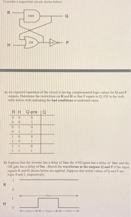
Consider a sequential circuit shown below. a) An expected operation of the circuit is having complemented logic values for and outputs. Determine the restrictions on and so that equals to . Fill in the truth table below with indicating the bad conditions or restricted cases b) Suppose that the inverter has a delay of Ins; the AND gates has a delay of 2ns; and the OR gate has a delay of . Sketch the waveforms at the outputs and if the input signals and shown below are applied. Suppose that initial values of and are logic 0 and 1 , respectively.