Home /
Expert Answers /
Electrical Engineering /
consider-the-ratio-control-scheme-shown-in-fig-15-6-each-flow-rate-is-measured-using-an-orifice-pa787
(Solved): Consider the ratio control scheme shown in Fig. 15.6. Each flow rate is measured using an orifice ...
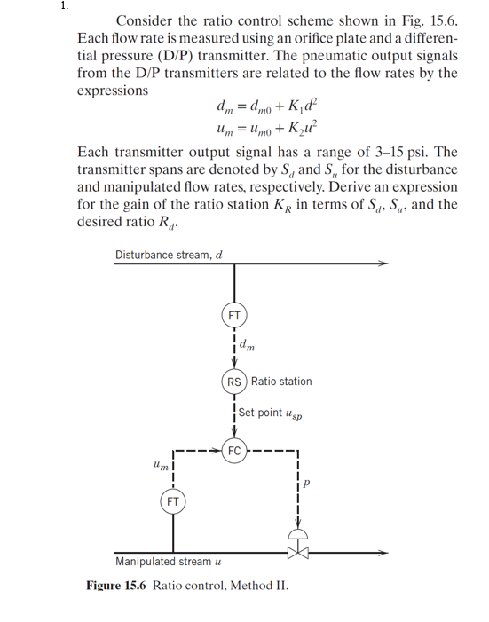
Consider the ratio control scheme shown in Fig. 15.6. Each flow rate is measured using an orifice plate and a differen- tial pressure (D/P) transmitter. The pneumatic output signals from the
(D)/(P)transmitters are related to the flow rates by the expressions
d_(m)=d_(m0)+K_(1)d^(2)
u_(m)=u_(m0)+K_(2)u^(2)
Each transmitter output signal has a range of
3-15\psi . The transmitter spans are denoted by
S_(d)and
S_(u)for the disturbance and manipulated flow rates, respectively. Derive an expression for the gain of the ratio station
K_(R)in terms of
S_(d),S_(u), and the desired ratio
R_(d). Figure 15.6 Ratio control, Method II.