Home /
Expert Answers /
Mechanical Engineering /
consider-the-shaft-shown-figure-1-that-has-a-diameter-d-4-6cm-the-length-of-each-segment-is-l-3m-pa588
(Solved): Consider the shaft shown (Figure 1) that has a diameter d=4.6cm. The length of each segment is L=3m ...
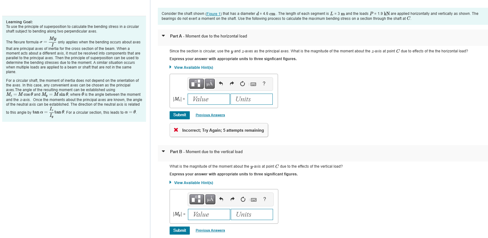
Consider the shaft shown (Figure 1) that has a diameter d=4.6cm. The length of each segment is L=3m and the loads P=1.9kN are applied horizontally and vertically as shown. The
Learning Goal:
To use the principle of superposition to calculate the bending stress in a circular
shaft subject to bending along two perpendicular axes.
The flexure formula \sigma =(My)/(I) only applies when the bending occurs about axes
that are principal axes of inertia for the cross section of the beam. When a
moment acts about a different axis, it must be resolved into components that are
parallel to the principal axes. Then the principle of superposition can be used to
determine the bending stresses due to the moment. A similar situation occurs
when multiple loads are applied to a beam or shaft that are not in the same
plane.
For a circular shaft, the moment of inertia does not depend on the orientation of
the axes. In this case, any convenient axes can be chosen as the principal
axes. The angle of the resulting moment can be established using
M_(z)=Mcos\theta and M_(y)=Msin\theta , where \theta is the angle between the moment
and the z-axis. Once the moments about the principal axes are known, the angle
of the neutral axis can be established. The direction of the neutral axis is related
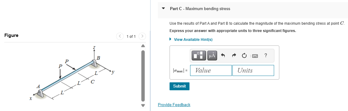
to this angle by tan\alpha =(I_(z))/(I_(y))tan\theta . For a circular section, this leads to \alpha =\theta . Part C - Maximum bending stress
Use the results of Part A and Part B to calculate the magnitude of the maximum bending stress at point C.
Figure
1 of 1
Express your answer with appropriate units to three significant figures.
View Available Hint(s)