Home /
Expert Answers /
Electrical Engineering /
consider-the-strain-gauge-circuit-below-figure-2-strain-gauge-measurement-system-a-part-mat-pa446
(Solved): Consider the strain-gauge circuit below: Figure 2: Strain-gauge measurement system. a. Part \( \mat ...
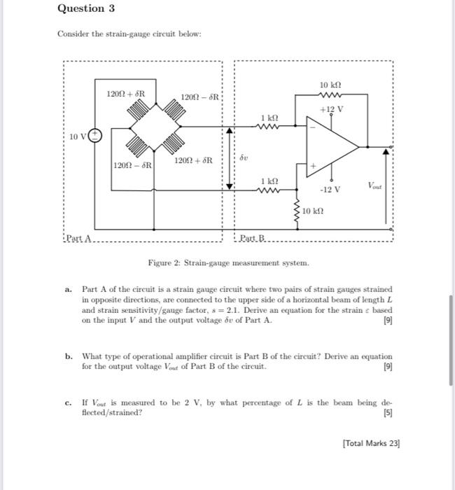
Consider the strain-gauge circuit below: Figure 2: Strain-gauge measurement system. a. Part \( \mathbf{A} \) of the circuit is a strain gauge circuit where two pairs of strain gauges strained in opposite directions, are connected to the upper side of a horizontal beam of length \( L \) and strain sensitivity/gauge factor, \( s=2.1 \). Derive an equation for the strain \( c \) based on the input \( V \) and the output voltage \( \delta v \) of Part \( A \). b. What type of operational amplifier circuit is Part B of the circuit? Derive an equation for the output voltage \( V_{\text {out }} \) of Part B of the circuit. c. If \( V_{\text {out }} \) is measured to be \( 2 \mathrm{~V} \), by what percentage of \( L \) is the beam being deflected/strained? [Total Marks 23]
Expert Answer
(a) The part-A is a Wheatstone's Bridge in which the resistance of the arm is cahnged in