Home /
Expert Answers /
Electrical Engineering /
consider-the-three-phase-inverter-circuit-of-fig-1-with-r-l-load-and-y-connected-source-with-r-2-0-pa437
(Solved): Consider the three-phase inverter circuit of Fig.1 with R-L load and Y-connected source with R=2.0 ...
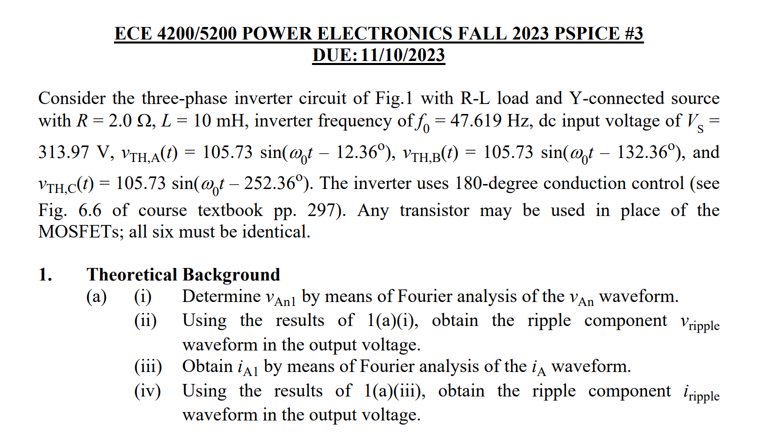
Consider the three-phase inverter circuit of Fig.1 with R-L load and Y-connected source with , inverter frequency of , dc input voltage of , and . The inverter uses 180 -degree conduction control (see Fig. 6.6 of course textbook pp. 297). Any transistor may be used in place of the MOSFETs; all six must be identical. 1. Theoretical Background (a) (i) Determine by means of Fourier analysis of the waveform. (ii) Using the results of 1(a)(i), obtain the ripple component waveform in the output voltage. (iii) Obtain by means of Fourier analysis of the waveform. (iv) Using the results of 1(a)(iii), obtain the ripple component waveform in the output voltage.