Home /
Expert Answers /
Civil Engineering /
consider-the-two-beam-problem-shown-in-figure-2-the-beams-are-of-length-l-pa474
(Solved): Consider the two-beam problem shown in Figure 2. The beams are of length \( L ...
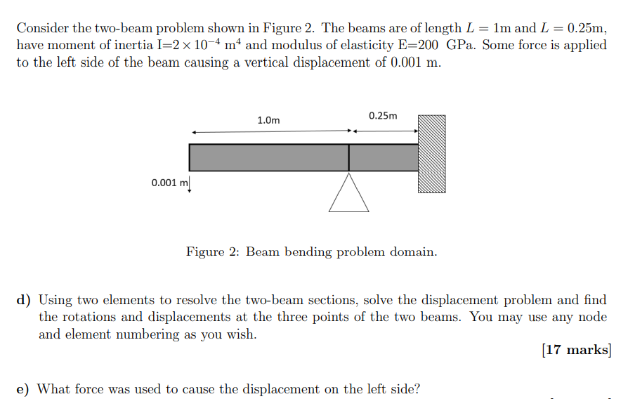
Consider the two-beam problem shown in Figure 2. The beams are of length \( L=1 \mathrm{~m} \) and \( L=0.25 \mathrm{~m} \), have moment of inertia \( \mathrm{I}=2 \times 10^{-4} \mathrm{~m}^{4} \) and modulus of elasticity \( \mathrm{E}=200 \) GPa. Some force is applied to the left side of the beam causing a vertical displacement of \( 0.001 \mathrm{~m} \). Figure 2: Beam bending problem domain. d) Using two elements to resolve the two-beam sections, solve the displacement problem and find the rotations and displacements at the three points of the two beams. You may use any node and element numbering as you wish. [17 marks] e) What force was used to cause the displacement on the left side?
Expert Answer
The beam element stiffness matrix k relates the shear forces and bending moments at the end of the beam {V1,M1,V2,M2} to the deflections and rotations