(Solved): D. Inverting amplifier The inverting amplifier circuit shown below uses an LMC660 op amp with +-8-V ...
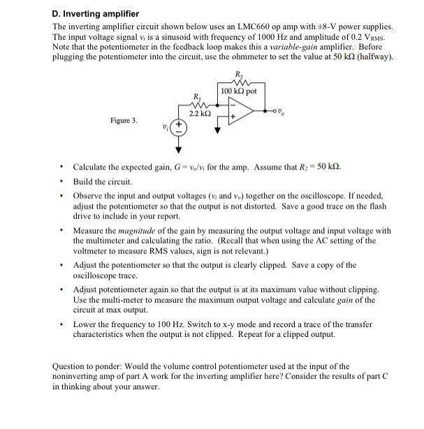
D. Inverting amplifier The inverting amplifier circuit shown below uses an LMC660 op amp with
+-8-V power supplies. The input voltage signal
v_(i)is a sinusoid with frequency of 1000 Hz and amplitude of 0.2 VRMs. Note that the potentiometer in the feedback loop makes this a variable-gain amplifier. Before plugging the potentiometer into the circuit, use the ohmmeter to set the value at
50k\Omega (halfway). Figure 3. Calculate the expected gain,
G=(v_(o))/(v_(i))for the amp. Assume that
R_(2)=50k\Omega . Build the circuit. Observe the input and output voltages (
v_(1)and
v_(0)) together on the oscilloscope. If needed, adjust the potentiometer so that the output is not distorted. Save a good trace on the flash drive to include in your report. Measure the magnitude of the gain by measuring the output voltage and input voltage with the multimeter and calculating the ratio. (Recall that when using the AC setting of the voltmeter to measure RMS values, sign is not relevant.) Adjust the potentiometer so that the output is clearly clipped. Save a copy of the oscilloscope trace. Adjust potentiometer again so that the output is at its maximum value without clipping. Use the multi-meter to measure the maximum output voltage and calculate gain of the circuit at max output. Lower the frequency to 100 Hz . Switch to
x-ymode and record a trace of the transfer characteristics when the output is not clipped. Repeat for a clipped output. Question to ponder: Would the volume control potentiometer used at the input of the noninverting amp of part A work for the inverting amplifier here? Consider the results of part C in thinking about your answer.