Home /
Expert Answers /
Electrical Engineering /
design-in-the-circuit-diagram-below-as-a-low-pass-filter-for-vo-output-with-a-cutoff-frequency-of-10-pa535
(Solved): Design in the circuit diagram below as a low-pass filter for Vo output with a cutoff frequency of 10 ...
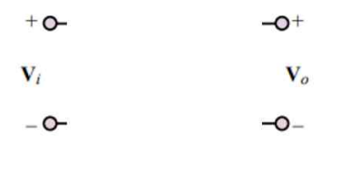
Design in the circuit diagram below as a low-pass filter for Vo output with a cutoff frequency of 10 Hz for Vi input using 1 ? R and C only once. (Write transfer function, differential equation for filter design, find C)

Expert Answer
Solution: To design the low pass filter that meets the given specifications as-The cut-off frequency fC of the filter circuit is equal to fc=10 Hz.Value of given resistor element R=1?.The structure of the first-order passive RC low pass filter is obtained when the output is taken across the capacitor element as -Transform the circuit into s-domain with all initial conditions considered to be zero.As, On drawing the s-domain circuit as-Using KVL in the closed mesh-