Home /
Expert Answers /
Electrical Engineering /
draw-the-circuit-in-figure-1-label-the-part-that-acts-as-a-filter-and-the-part-that-acts-as-a-buff-pa717
(Solved): -Draw the circuit in Figure 1. Label the part that acts as a filter and the part that acts as a buff ...
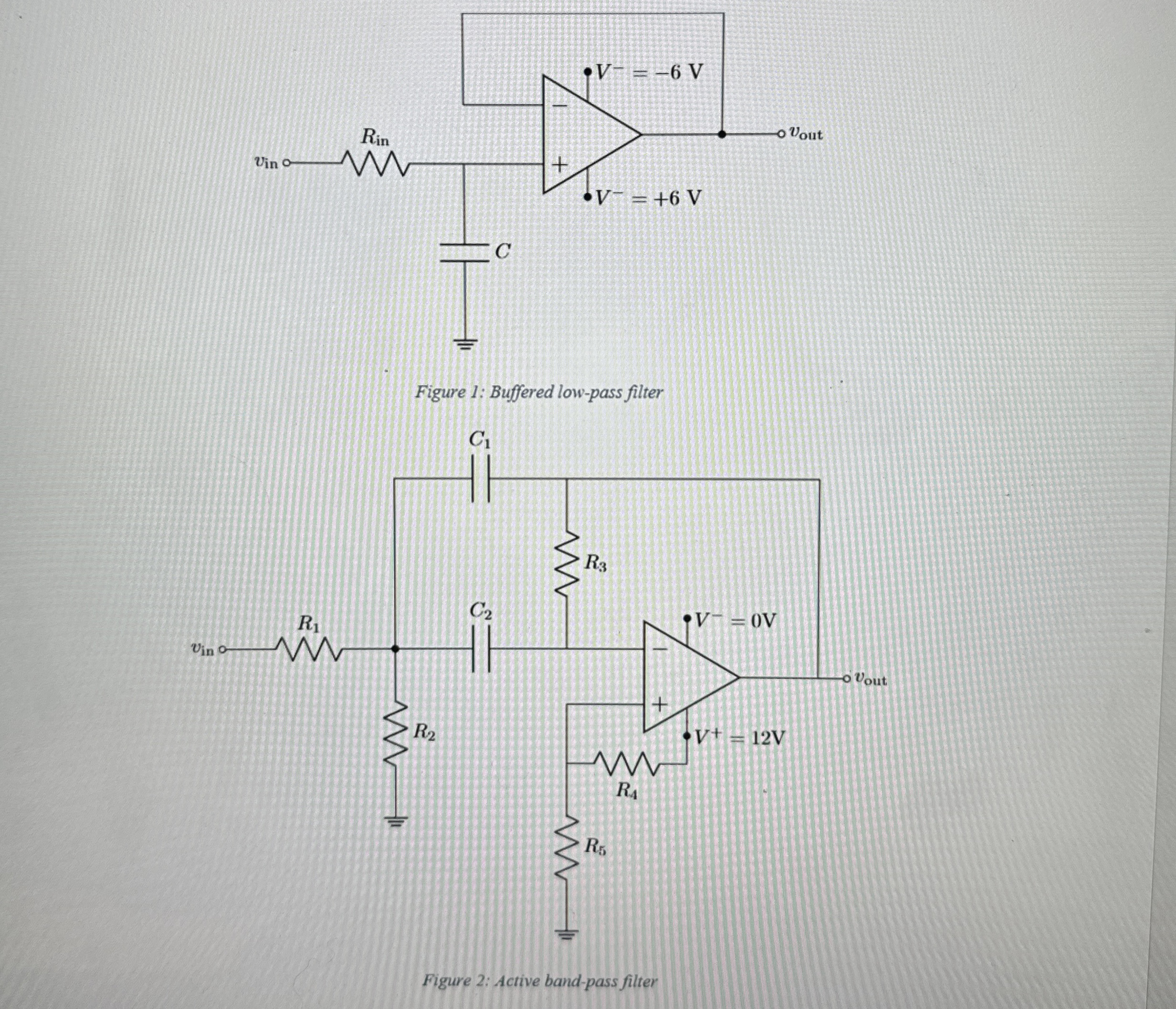
-Draw the circuit in Figure 1. Label the part that acts as a filter and the part that acts as a buffer. Let
R_(in)=13k\Omega and
C=13.6nF. What is the -3 dB cutoff frequency of the filter? -What's the DC value of
v_(out )shown in Figure 2 -In Figure 2, let
C_(1)=C_(2)=6.8nFso that our resistors have reasonable values. Choose the values of resistors 1 through 4 such that you have
V_(1)=6VDC, quality
Q=5, unity gain
A_(v), and center frequency
f_(0)=900Hz:
R_(1)=(Q)/(A_(v)\omega _(0)C_(1))
R_(2)=(Q)/((2Q^(2)-A_(v))\omega _(0)C_(1))
R_(3)=(2Q)/(\omega _(0)C_(1))