(Solved): Draw the timing diagram for the following control signals on the diagram below when the WIMP51 is ex ...
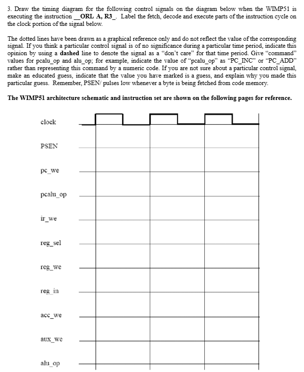
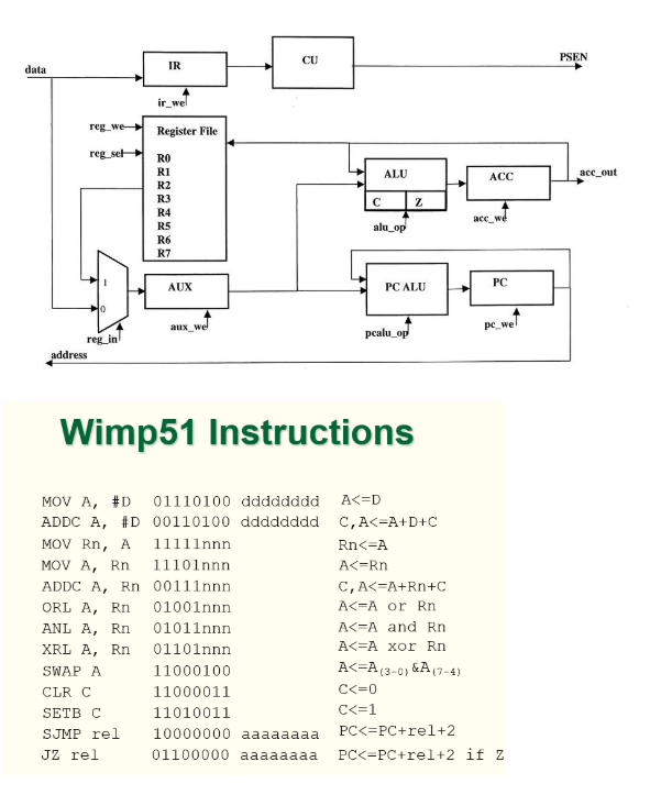
Draw the timing diagram for the following control signals on the diagram below when the WIMP51 is executing the instruction _(). Label the fetch, decode and execute parts of the instruction cycle on the clock portion of the signal below. The dotted lines have been drawn as a graphical reference only and do not reflect the value of the corresponding signal. If you think a particular control signal is of no significance during a particular time period, indicate this opinion by using a dashed line to denote the signal as a "don't care" for that time period. Give "command" values for pcalu_(o)p and alu_(o)p; for example, indicate the value of "pcalu_(o)p" as "PC_(I)NC" or "PC_(A)DD" rather than representing this command by a numeric code. If you are not sure about a particular control signal, make an educated guess, indicate that the value you have marked is a guess, and explain why you made this particular guess. Remember, PSE(N)/( p)ulses low whenever a byte is being fetched from code memory. The WIMP51 architecture schematic and instruction set are shown on the following pages for reference. Wimp51 Instructions