Home /
Expert Answers /
Mechanical Engineering /
draw-the-velocity-and-acceleration-diagram-for-the-mechanism-shown-in-figure-3-and-find-the-velocit-pa858
(Solved): Draw the velocity and acceleration diagram for the mechanism shown in Figure 3 and find the velocit ...
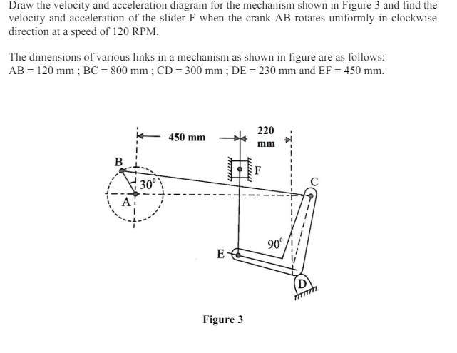
Draw the velocity and acceleration diagram for the mechanism shown in Figure 3 and find the velocity and acceleration of the slider
Fwhen the crank
ABrotates uniformly in clockwise direction at a speed of 120 RPM. The dimensions of various links in a mechanism as shown in figure are as follows:
AB=120mm;BC=800mm;CD=300mm;DE=230mmand
EF=450mm. Figure 3