Home /
Expert Answers /
Electrical Engineering /
drwa-the-ladder-diagram-design-a-ladder-diagram-to-control-the-level-of-a-water-storage-tank-pa326
(Solved): Drwa the ladder diagram. Design a ladder diagram to control the level of a water storage tank; ...
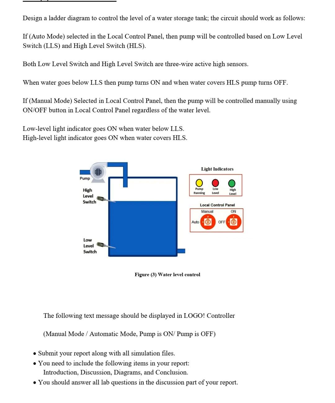
Drwa the ladder diagram.
Design a ladder diagram to control the level of a water storage tank; the circuit should work as follows: If (Auto Mode) selected in the Local Control Panel, then pump will be controlled based on Low Level Switch (LLS) and High Level Switch (HLS). Both Low Level Switch and High Level Switch are three-wire active high sensors. When water goes below LLS then pump turns ON and when water covers HLS pump turns OFF. If (Manual Mode) Selected in Local Control Panel, then the pump will be controlled manually using ON/OFF button in Local Control Panel regardless of the water level. Low-level light indicator goes ON when water below LLS. High-level light indicator goes ON when water covers HLS. Figure (3) Water level control The following text message should be displayed in LOGO! Controller (Manual Mode / Automatic Mode, Pump is ON/ Pump is OFF) - Submit your report along with all simulation files. - You need to include the following items in your report: Introduction, Discussion, Diagrams, and Conclusion. - You should answer all lab questions in the discussion part of your report.