Home /
Expert Answers /
Electrical Engineering /
e-an-rlc-circuit-is-shown-in-the-diagram-below-in-figure-5-determine-the-transfer-function-of-t-pa289
(Solved): e) An RLC circuit is shown in the diagram below in Figure 5. Determine the transfer function of t ...
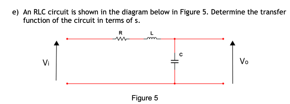
e) An RLC circuit is shown in the diagram below in Figure 5. Determine the transfer function of the circuit in terms of s. R L m ww C Vo Vi Figure 5 H
f) Using the standard second order equation, show how the electrical circuit shown in Figure 5 can be used to model the spring mass damper system shown in Figure 4 if appropriate component values are selected. If the capacitor value is fixed at 200?F what value of R and L would be required?