Home /
Expert Answers /
Electrical Engineering /
fig-1-shows-a-single-phase-controlled-rectifier-connected-across-a-resistive-inductive-r-l-load-pa431
(Solved): Fig. 1 shows a single-phase controlled rectifier connected across a resistive-inductive (R-L) load ...
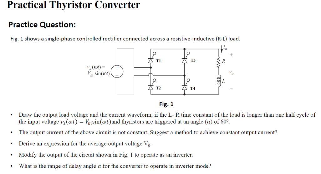
Fig. 1 shows a single-phase controlled rectifier connected across a resistive-inductive (R-L) load. Fig. 1 - Draw the output load voltage and the current waveform, if the L-R time constant of the load is longer than one half cycle of the input voltage and thyristors are triggered at an angle of . - The output current of the above circuit is not constant. Suggest a method to achieve constant output current? - Derive an expression for the average output voltage . - Modify the output of the circuit shown in Fig. 1 to operate as an inverter. - What is the range of delay angle for the converter to operate in inverter mode?