Home /
Expert Answers /
Electrical Engineering /
figure-02-shows-the-circuit-diagram-of-an-mathrm-ac-voltage-controller-figure-02-the-cont-pa763
(Solved): Figure 02 shows the circuit diagram of an \( \mathrm{AC} \) voltage controller. Figure 02 The cont ...
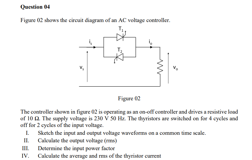
Figure 02 shows the circuit diagram of an \( \mathrm{AC} \) voltage controller. Figure 02 The controller shown in figure 02 is operating as an on-off controller and drives a resistive load of \( 10 \Omega \). The supply voltage is \( 230 \mathrm{~V} 50 \mathrm{~Hz} \). The thyristors are switched on for 4 cycles and off for 2 cycles of the input voltage. I. Sketch the input and output voltage waveforms on a common time scale. II. Calculate the output voltage (rms) III. Determine the input power factor IV. Calculate the average and rms of the thyristor current