Home /
Expert Answers /
Electrical Engineering /
figure-1-shows-a-single-line-diagram-of-a-60-hz-synchronous-generator-connected-to-an-infinite-bus-t-pa849
(Solved): Figure 1 shows a single-line diagram of a 60 Hz synchronous generator connected to an infinite bus t ...
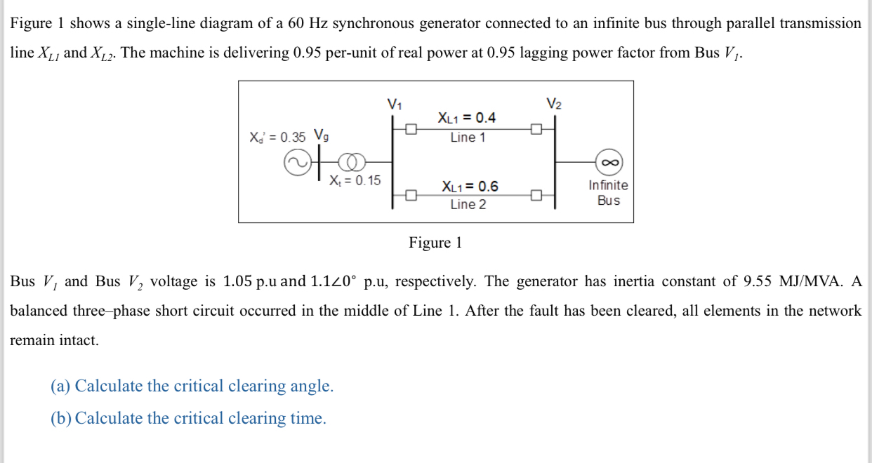
Figure 1 shows a single-line diagram of a 60 Hz synchronous generator connected to an infinite bus through parallel transmission line
x_(L1)and
x_(L2). The machine is delivering 0.95 per-unit of real power at 0.95 lagging power factor from Bus
V_(l). Figure 1 Bus
V_(1)and Bus
V_(2)voltage is
1.05p.uand
(1.1)/(_(0))\deg p.u, respectively. The generator has inertia constant of
9.55M(J)/(M)VA. A balanced three-phase short circuit occurred in the middle of Line 1. After the fault has been cleared, all elements in the network remain intact. (a) Calculate the critical clearing angle. (b) Calculate the critical clearing time.