Home /
Expert Answers /
Chemical Engineering /
figure-2-block-diagram-of-cruise-control-closed-loop-system-the-transfer-function-for-the-vehicle-pa783
(Solved): Figure 2. Block Diagram of Cruise Control Closed-Loop System The transfer function for the vehicle ...
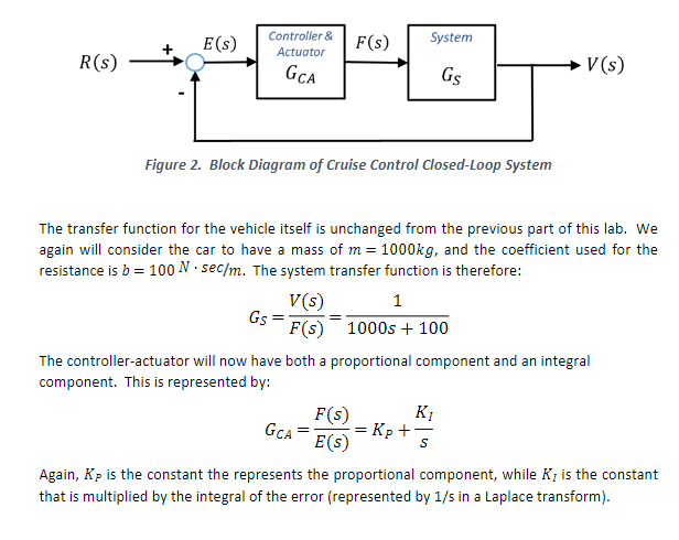
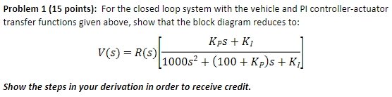
Figure 2. Block Diagram of Cruise Control Closed-Loop System The transfer function for the vehicle itself is unchanged from the previous part of this lab. We again will consider the car to have a mass of , and the coefficient used for the resistance is . The system transfer function is therefore: The controller-actuator will now have both a proportional component and an integral component. This is represented by: Again, is the constant the represents the proportional component, while is the constant that is multiplied by the integral of the error (represented by in a Laplace transform).
Problem 1 (15 points): For the closed loop system with the vehicle and PI controller-actuator transfer functions given above, show that the block diagram reduces to: Show the steps in your derivation in order to receive credit.