Home /
Expert Answers /
Electrical Engineering /
figure-4-13-perform-a-transient-analysis-using-the-circuit-of-figure-4-plot-the-output-signal-on-pa241
(Solved): Figure 4 13. Perform a transient analysis using the circuit of Figure 4. Plot the output signal (on ...
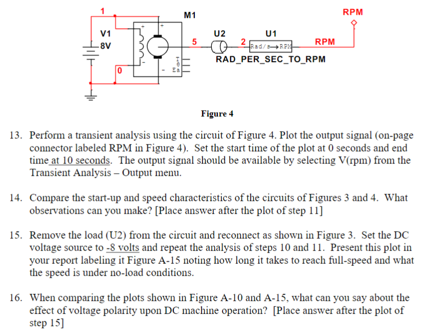
Figure 4 13. Perform a transient analysis using the circuit of Figure 4. Plot the output signal (on-page connector labeled RPM in Figure 4). Set the start time of the plot at 0 seconds and end time at 10 seconds. The output signal should be available by selecting V(rpm) from the Transient Analysis - Output menu. 14. Compare the start-up and speed characteristics of the circuits of Figures 3 and 4. What observations can you make? [Place answer after the plot of step 11] 15. Remove the load (U2) from the circuit and reconnect as shown in Figure 3. Set the DC your report labeling it Figure A-15 noting how long it takes to reach full-speed and what the speed is under no-load conditions. 16. When comparing the plots shown in Figure A-10 and A-15, what can you say about the effect of voltage polarity upon DC machine operation? [Place answer after the plot of step 15]