(Solved): In this project, you will design a simple traffic light control logic circuit. Suppose thetraffic li ...
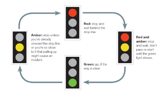
In this project, you will design a simple traffic light control logic circuit. Suppose the
traffic light sequence is red, red and amber, green, amber and then red again as shown below.
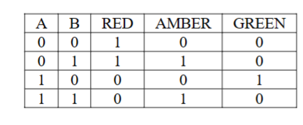
Say you are to design a combinational logic circuit to convert two-digit binary input
(name them as A and B) to three output functions (name them as RED, AMBER and
GREEN) that are directly connected to lights to activate/deactivate as needed. The
following truth table shows all input/output combinations.
Simplify three output functions (RED, AMBER and GREEN). Then, design a
traffic control logic circuit using the simplified logic functions. Make sure to use three digital LED components as output devices. Also, make sure to change their colors to Red, Orange, and Green to make your design more realistic.
Test your circuit by providing different AB bit patterns. Do not use test bench feature of circuitverse.