Home /
Expert Answers /
Electrical Engineering /
measure-and-record-the-effects-of-negative-feedback-on-a-voltage-amplifier-the-amplifier-which-is-pa150
(Solved): Measure and record the effects of negative feedback on a voltage amplifier. The amplifier which is ...
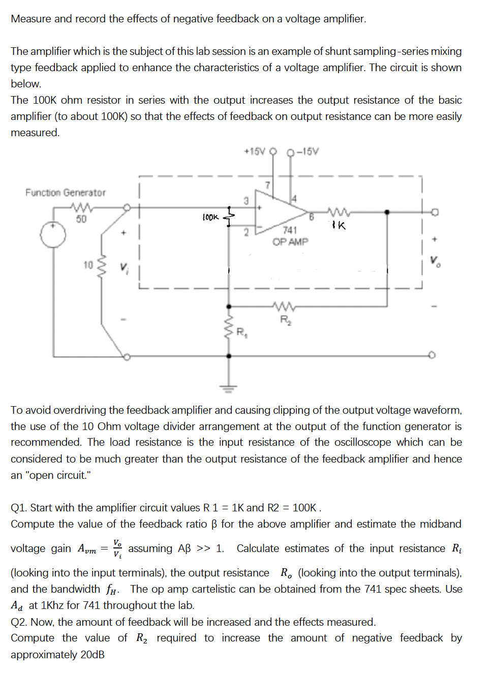
Measure and record the effects of negative feedback on a voltage amplifier. The amplifier which is the subject of this lab session is an example of shunt sampling-series mixing type feedback applied to enhance the characteristics of a voltage amplifier. The circuit is shown below. The ohm resistor in series with the output increases the output resistance of the basic amplifier (to about 100K) so that the effects of feedback on output resistance can be more easily measured. To avoid overdriving the feedback amplifier and causing clipping of the output voltage waveform, the use of the voltage divider arrangement at the output of the function generator is recommended. The load resistance is the input resistance of the oscilloscope which can be considered to be much greater than the output resistance of the feedback amplifier and hence an "open circuit." Q1. Start with the amplifier circuit values and . Compute the value of the feedback ratio for the above amplifier and estimate the midband voltage gain assuming . Calculate estimates of the input resistance (looking into the input terminals), the output resistance (looking into the output terminals), and the bandwidth . The op amp cartelistic can be obtained from the sheets. Use at for 741 throughout the lab. Q2. Now, the amount of feedback will be increased and the effects measured. Compute the value of required to increase the amount of negative feedback by approximately