Home /
Expert Answers /
Mechanical Engineering /
nbsp-question-2-a-spring-controlled-lever-is-shown-in-fig-1-below-the-spring-is-to-be-inserte-pa916
(Solved): Question 2 A spring-controlled lever is shown in fig. 1 below. The spring is to be inserte ...
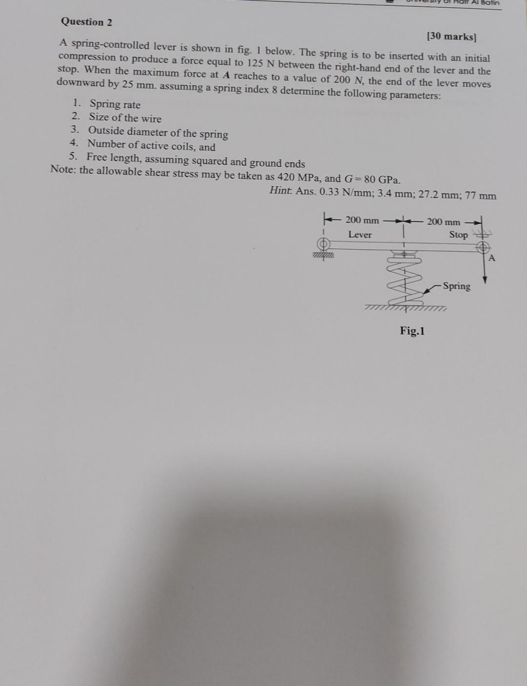
Question 2 A spring-controlled lever is shown in fig. 1 below. The spring is to be inserted with an initial compression to produce a force equal to \( 125 \mathrm{~N} \) between the right-hand end of the lever and the stop. When the maximum force at \( \boldsymbol{A} \) reaches to a value of \( 200 \mathrm{~N} \), the end of the lever moves downward by \( 25 \mathrm{~mm} \). assuming a spring index 8 determine the following parameters: 1. Spring rate 2. Size of the wire 3. Outside diameter of the spring 4. Number of active coils, and 5. Free length, assuming squared and ground ends Note: the allowable shear stress may be taken as \( 420 \mathrm{MPa} \), and \( G=80 \mathrm{GPa} \). Hint. Ans. \( 0.33 \mathrm{~N} / \mathrm{mm} ; 3.4 \mathrm{~mm} ; 27.2 \mathrm{~mm} ; 77 \mathrm{~mm} \)
Expert Answer
The answer is shown in the below. Please refer the below image for the detailed solution.