(Solved): PART A:- DC CIRCUIT ANALYSIS Refer to Figure 1 (a) circuit A and (b) circuit B. A) Obtain the branch ...
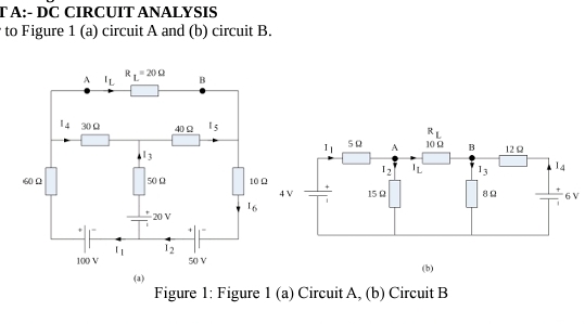
PART A:- DC CIRCUIT ANALYSIS Refer to Figure 1 (a) circuit A and (b) circuit B. A) Obtain the branch currents for the circuits in Figure 1 (a) and (b) by applying each of the following methods:- (a) Branch current method (b) Mesh analysis (c) Nodal analysis (d) Source transformation (e) Superposition theorem B) Obtain the Thevenins equivalent circuit viewed at the load terminals
Aand
Bof
R_(L)for the circuits in Figure 1. C) Obtain the Norton's equivalent circuit viewed at the load terminals
Aand
Bof
R_(L)for the circuits in Figure 1. D) Let
R_(L)be a variable resistor with values:
0,5,10,15,20,25,30,35,40,45,50\Omega . i. Determine the power absorbed by the load for each load value in each circuit. ii. Plot the power absorbed by the load against the load resistance values provided iii. Show that at the maximum power point of the plots, the load resistance is equal to the Thevenin's equivalent resistances (part B). E) Use MATLAB simulink to model the circuits in Figure 1. Connect appropriate blocks in order to display the branch currents, voltage drops, power absorbed by each element and power supplied by each source. Do this with the values:- (a) provided, (b) with
R_(L)=R_(TH)
(1)/(2)? A:- DC CIRCUIT ANALYSIS to Figure 1 (a) circuit A and (b) circuit B. (a) Figure 1: Figure 1 (a) Circuit A, (b) Circuit B