Home /
Expert Answers /
Electrical Engineering /
part-iii-maximum-power-transfer-for-the-circuit-of-fig-3a-let-e-12-v-r-1-1k2-omega-r-2-1-pa272
(Solved): PART III - MAXIMUM POWER TRANSFER For the circuit of Fig 3a, let: E=12[V],R_(1)=1k2[\Omega ],R_(2)=1 ...
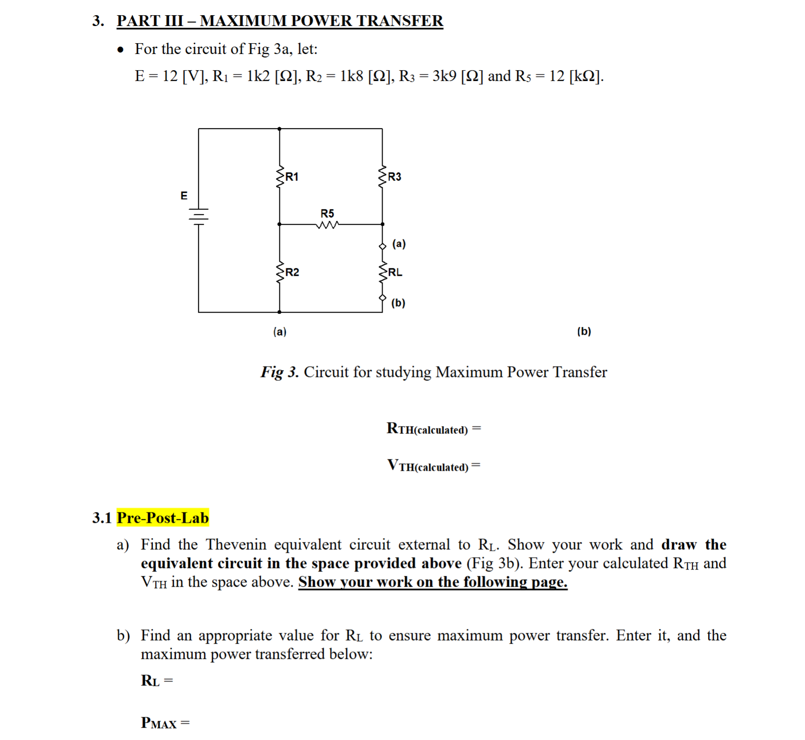
PART III - MAXIMUM POWER TRANSFER
For the circuit of Fig 3a, let:
E=12[V],R_(1)=1k2[\Omega ],R_(2)=1k8[\Omega ],R_(3)=3k9[\Omega ] and R_(5)=12[k\Omega ]
(b)
Fig 3. Circuit for studying Maximum Power Transfer
R_(TH (calculated) )=
V_(TH( calculated ))=
3.1 Pre-Post-Lab
aR_(L). Show your work and draw the
equivalent circuit in the space provided above ( Fig 3 b ). Enter your calculated R_(TH) and
V_(TH) in the space above. Show your work on the following page.
bR_(L) to ensure maximum power transfer. Enter it, and the
maximum power transferred below:
R_(L)=
P_(MAx)=

What is RTH, VTH, RL, and Pmax?