Home /
Expert Answers /
Electrical Engineering /
please-help-with-both-part-1-and-2-based-on-the-timing-diagram-for-a-3-bit-counter-and-the-figure-1-pa141
(Solved): Please help with both Part 1 and 2 based on the timing diagram for a 3 bit counter and the Figure 1 ...
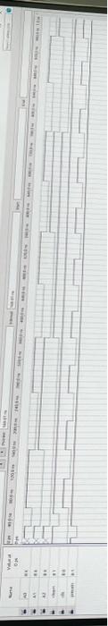
Please help with both Part 1 and 2 based on the timing diagram for a 3 bit counter and the Figure 1 diagram.
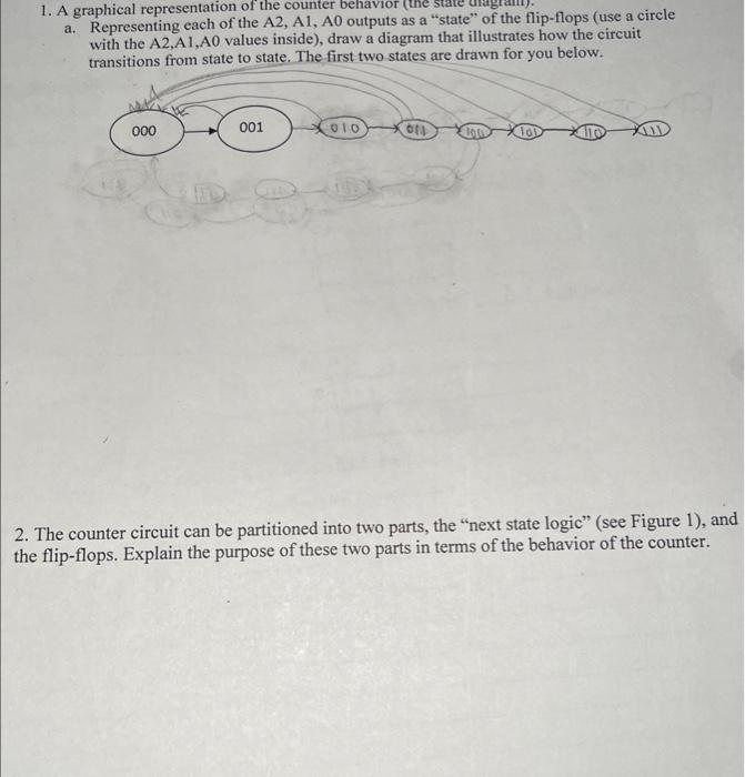
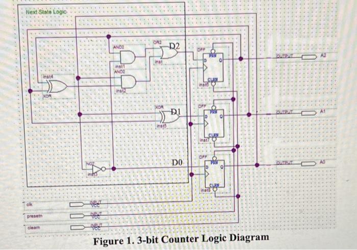
1. A graphical representation of the counter behavior (twe state ate" of the flip-flops (use a circle a. Representing each of the A2, A1, A0 outputs as a "state" of the flip-flops (use a circl with the A2,A1, A0 values inside), draw a diagram that illustrates how the circt 2. The counter circuit can be partitioned into two parts, the "next state logic" (see Figure 1), and the flip-flops. Explain the purpose of these two parts in terms of the behavior of the counter.
\( \pi_{3}^{5} \) * \( 8 \div 35 \) ? \( 75 \% \) ?? 4 (4) \( 4 \times 14 \)
Figure 1. 3-bit Counter Logic Diagram