Home /
Expert Answers /
Electrical Engineering /
please-solve-this-circuits-question-3-preliminary-work-pre-lab-1-in-the-circuit-shown-in-figure-pa944
(Solved): please solve this circuits question 3 Preliminary Work (Pre-Lab) 1. In the circuit shown in Figure ...
please solve this circuits question
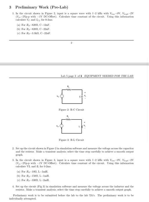
3 Preliminary Work (Pre-Lab) 1. In the circuit shown in Figure 2, iaput is a sepuafe wave with with -p with + IV DC-Offart . Cakculate time constant of the circuit. Using this information calculate and , for max (a) For . (b) For 8200n, . (c) For . 2 Lab 5 page 3 of 4 EQUIPMENT NEEDED FOR THE LAB: Figure 2: R-C Circuit Figure 3: R-L Circuit 2. Set up the circuit shown in Figure 2 in simulation soft ware and measure the voltage acroes the capacitor and the resistor. Make a transient analysic; select the time step carefully to achisove a smooth output jraph. 3. In the circait shown in Figure 3, ingut is a spate wave with with p with + IV DC-Offet . Calculate time constant of the circuit. Using this infornuation colculate VL and il, for 0-2ms. (a) For . (b) For . (c) For - . resistor. Make a transient analysis; select the time step carefully to achieve a smooth output graph. Preliminary work is to be submitted before the lab to the lab TA's. The preliminary work is to be individually atteupted.