Home /
Expert Answers /
Electrical Engineering /
problem-01-second-order-lrc-parallel-circuit-in-fig-p1a-below-the-switch-has-been-closed-for-a-ver-pa764
(Solved): PROBLEM 01: Second Order LRC Parallel Circuit In Fig. P1a below the switch has been closed for a ver ...
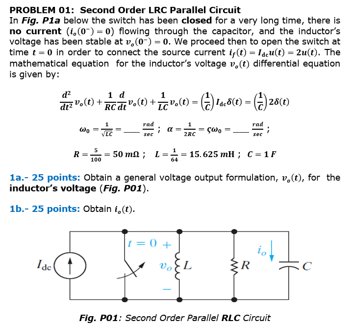
PROBLEM 01: Second Order LRC Parallel Circuit
In Fig. P1a below the switch has been closed for a very long time, there is no current (i_(o)(0^(-))=0) flowing through the capacitor, and the inductor's voltage has been stable at v_(o)(0^(-))=0. We proceed then to open the switch at time t=0 in order to connect the source current i_(f)(t)=I_(dc)u(t)=2u(t). The mathematical equation for the inductor's voltage v_(o)(t) differential equation is given by:
(d^(2))/(dt^(2))v_(o)(t)+(1)/(RC)(d)/(dt)v_(o)(t)+(1)/(LC)v_(o)(t)=((1)/(C))I_(dc)\delta (t)=((1)/(C))2\delta (t)
\omega _(0)=(1)/(\sqrt(LC))=dots(rad)/(sec);\alpha =(1)/(2RC)=?\omega _(0)=dots(rad)/(sec);
R=(5)/(100)=50m\Omega ;,L=(1)/(64)=15.625mH;,C=1F
1a.- 25 points: Obtain a general voltage output formulation, v_(o)(t), for the inductor's voltage (Fig. PO1).
1b.- 25 points: Obtain i_(o)(t).