Home /
Expert Answers /
Mechanical Engineering /
problem-2-compute-internal-forces-compute-the-internal-forces-at-each-of-the-annotated-points-a-g-pa372
(Solved): Problem 2: Compute internal forces Compute the internal forces at each of the annotated points (A-G) ...
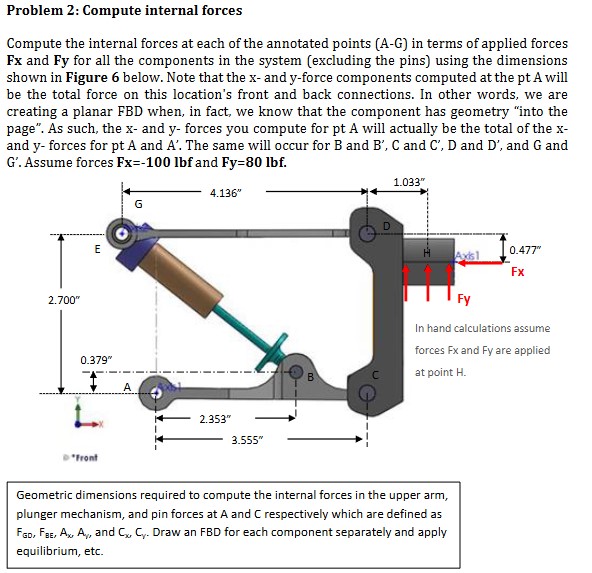
Problem 2: Compute internal forces
Compute the internal forces at each of the annotated points (A-G) in terms of applied forces
Fx and Fy for all the components in the system (excluding the pins) using the dimensions
shown in Figure 6 below. Note that the x - and y -force components computed at the pt A will
be the total force on this location's front and back connections. In other words, we are
creating a planar FBD when, in fact, we know that the component has geometry "into the
page". As such, the x - and y - forces you compute for pt A will actually be the total of the x -
and y - forces for pt A and A^('). The same will occur for B and B^('),C and C^('),D and D^('), and G and
G^('). Assume forces Fx=-100lbf and Fy=80lbf.
Geometric dimensions required to compute the internal forces in the upper arm,
plunger mechanism, and pin forces at A and C respectively which are defined as
F_(GD),F_(BE),A_(x),A_(v), and C_(x),C_(y). Draw an FBD for each component separately and apply
equilibrium, etc.