(Solved): PROBLEM 2: Design a 4-bar linkage with the left link represented as vector W and the right link as v ...
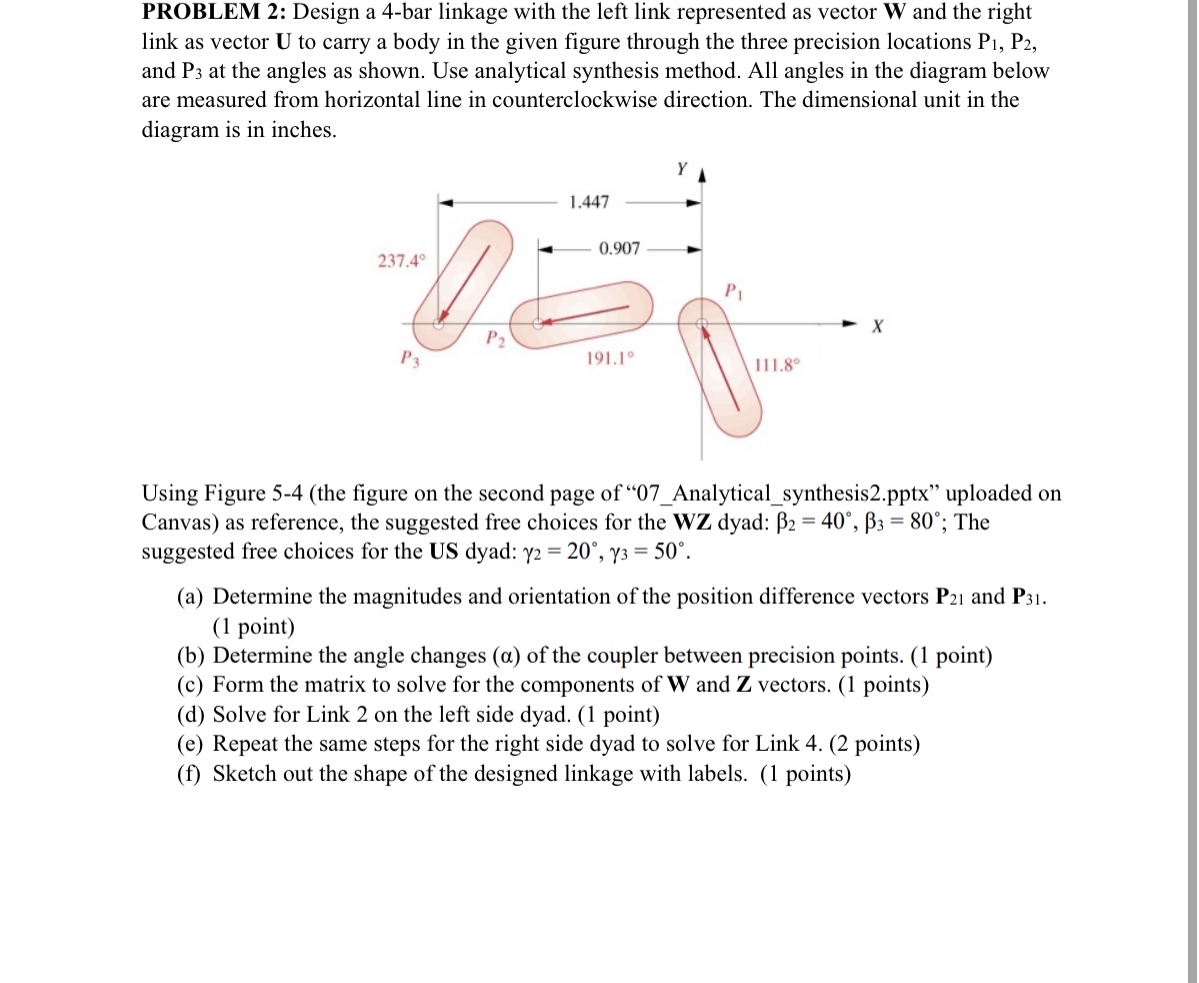
PROBLEM 2: Design a 4-bar linkage with the left link represented as vector
Wand the right link as vector
Uto carry a body in the given figure through the three precision locations
P_(1),P_(2), and
P_(3)at the angles as shown. Use analytical synthesis method. All angles in the diagram below are measured from horizontal line in counterclockwise direction. The dimensional unit in the diagram is in inches. Using Figure 5-4 (the figure on the second page of "07_Analytical_synthesis2.pptx" uploaded on Canvas) as reference, the suggested free choices for the
WZdyad:
\beta _(2)=40\deg ,\beta _(3)=80\deg ; The suggested free choices for the US dyad:
\gamma _(2)=20\deg ,\gamma _(3)=50\deg . (a) Determine the magnitudes and orientation of the position difference vectors
P_(21)and
P_(31). (1 point) (b) Determine the angle changes
(\alpha )of the coupler between precision points. (1 point) (c) Form the matrix to solve for the components of
Wand
Zvectors. (1 points) (d) Solve for Link 2 on the left side dyad. (1 point) (e) Repeat the same steps for the right side dyad to solve for Link 4. (2 points) (f) Sketch out the shape of the designed linkage with labels. (1 points)