Home /
Expert Answers /
Electrical Engineering /
procedure-1-for-the-parallel-circuit-in-figure-1-calculate-or-determine-the-following-r-t-pa270
(Solved): Procedure: 1. For the parallel circuit in Figure 1 , calculate or determine the following: \( R_{T ...
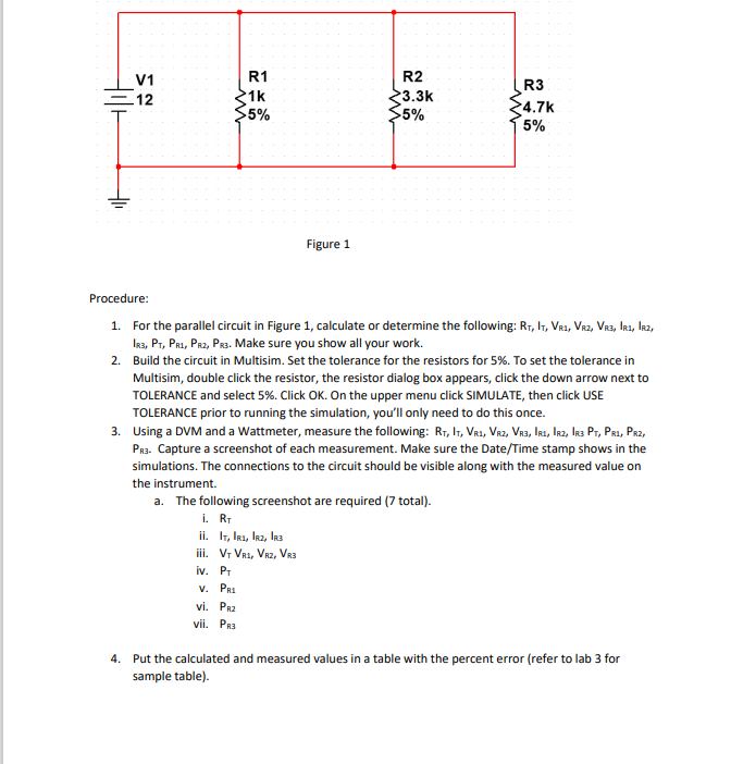
Procedure: 1. For the parallel circuit in Figure 1 , calculate or determine the following: \( R_{T}, I_{T}, V_{R 1}, V_{R 2}, V_{R 3}, I_{R 1}, I_{R 2} \), \( I_{\mathrm{R} 3}, \mathrm{P}_{\mathrm{T}}, \mathrm{P}_{\mathrm{R} 1}, \mathrm{P}_{\mathrm{R} 2}, \mathrm{P}_{\mathrm{R} 3} \). Make sure you show all your work. 2. Build the circuit in Multisim. Set the tolerance for the resistors for \( 5 \% \). To set the tolerance in Multisim, double click the resistor, the resistor dialog box appears, click the down arrow next to TOLERANCE and select 5\%. Click OK. On the upper menu click SIMULATE, then click USE TOLERANCE prior to running the simulation, you'll only need to do this once. 3. Using a DVM and a Wattmeter, measure the following: \( R_{T}, I_{T}, V_{R 1}, V_{R 2}, V_{R 3}, I_{R 1}, I_{R 2}, I_{R 3} P_{T}, P_{R 1}, P_{R 2} \), simulations. The connections to the circuit should be visible along with the measured value on the instrument. a. The following screenshot are required (7 total). i. \( \mathrm{R}_{\mathrm{T}} \) ii. \( \mathrm{I}_{\mathrm{T}}, \mathrm{I}_{\mathrm{R} 1}, \mathrm{I}_{\mathrm{R} 2}, \mathrm{I}_{\mathrm{R} 3} \) iii. \( \mathrm{V}_{\mathrm{T}} \mathrm{V}_{\mathrm{R} 1}, \mathrm{~V}_{\mathrm{R} 2}, \mathrm{~V}_{\mathrm{R} 3} \) iv. \( P_{T} \) V. \( P_{R 1} \) vi. \( P_{\text {R2 }} \) vii. \( \mathrm{P}_{\mathrm{R3}} \) 4. Put the calculated and measured values in a table with the percent error (refer to lab 3 for sample table).