Home /
Expert Answers /
Electrical Engineering /
procedure-3-simplification-of-combinational-logic-circuits-as-more-gates-are-added-on-to-a-logic-c-pa649
(Solved): Procedure 3: Simplification of Combinational Logic Circuits As more gates are added on to a logic c ...
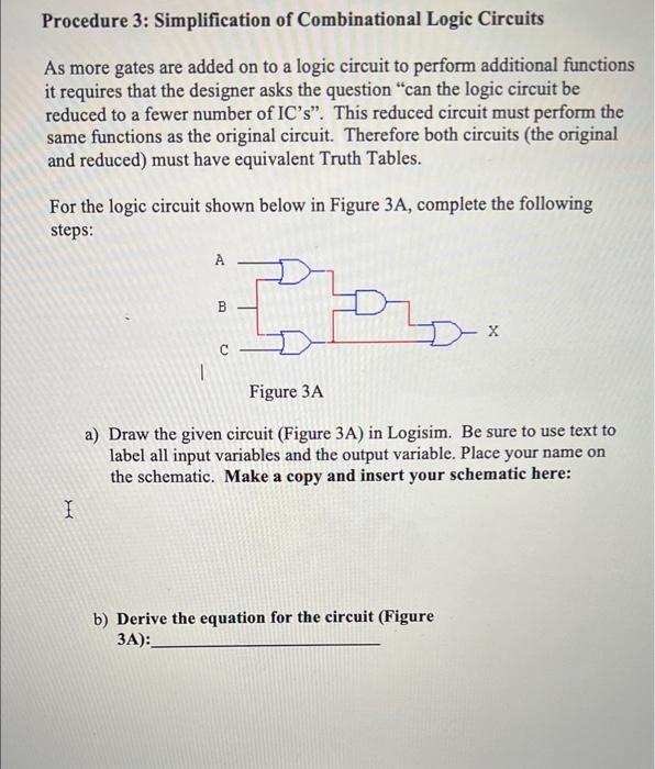
Procedure 3: Simplification of Combinational Logic Circuits As more gates are added on to a logic circuit to perform additional functions it requires that the designer asks the question "can the logic circuit be reduced to a fewer number of IC's". This reduced circuit must perform the same functions as the original circuit. Therefore both circuits (the original and reduced) must have equivalent Truth Tables. For the logic circuit shown below in Figure 3A, complete the following steps: A X Figure 3A a) Draw the given circuit (Figure 3A) in Logisim. Be sure to use text to label all input variables and the output variable. Place your name on the schematic. Make a copy and insert your schematic here: I b) Derive the equation for the circuit (Figure 3A): B
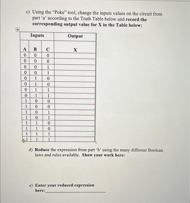
c) Using the "Poke" tool, change the inputs values on the circuit from part 'a' according to the Truth Table below and record the corresponding output value for X in the Table below: Inputs Output B X 0 0 1 0 1 1 0 1 1 0 1 1 1 1 1 d) Reduce the expression from part 'b' using the many different Boolean laws and rules available. Show your work here: e) Enter your reduced expression here: A 0 0 0 0 0 0 0 0 1 1 1 1 1 0 0 0 1 1 1 1 0 0 0 . C 0 0 1 1 0 0 1 1 0
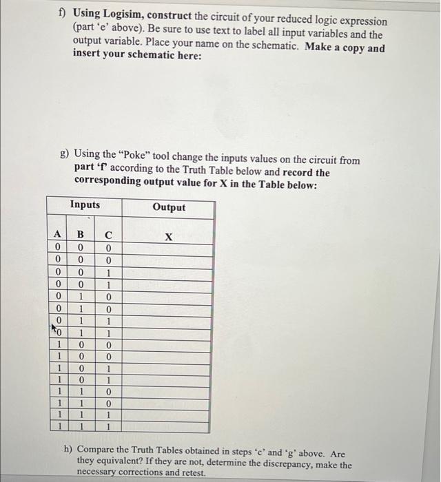
f) Using Logisim, construct the circuit of your reduced logic expression (part 'e' above). Be sure to use text to label all input variables and the output variable. Place your name on the schematic. Make a copy and insert your schematic here: g) Using the "Poke" tool change the inputs values on the circuit from part 'f' according to the Truth Table below and record the corresponding output value for X in the Table below: Inputs Output X 0 1 0 1 1 0 1 0 1 1 1 1 1 1 h) Compare the Truth Tables obtained in steps 'e' and 'g' above. Are they equivalent? If they are not, determine the discrepancy, make the necessary corrections and retest. AO A B 0 0 0 0 0 0 0 0 0 ¹0 1 1 1 1 1 1 0 1 1 1 1 0 0 C 0 0 1 1 0 0 1 1 0 0
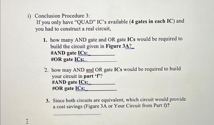
i) Conclusion Procedure 3: If you only have "QUAD" IC's available (4 gates in each IC) and you had to construct a real circuit, 1. how many AND gate and OR gate ICs would be required to build the circuit given in Figure 3A? #AND gate ICS: #OR gate ICS: 2. how may AND and OR gate ICs would be required to build your circuit in part 'f'? #AND gate ICS: #OR gate ICS: 3. Since both circuits are equivalent, which circuit would provide a cost savings (Figure 3A or Your Circuit from Part f)? I
Expert Answer
a) b) X= (A+B).(B+C)+C c) Inputs Output A B C X 0 0 0 0 0 0 1 1 0 1 0 1 0 1 1 1 1 0 0 0 1 0 1 1