Home /
Expert Answers /
Electrical Engineering /
procedure-a-solve-the-following-circuits-using-hand-calculations-a-voltage-divider-circuit-i-pa759
(Solved): Procedure: a. Solve the following circuits using hand calculations a. Voltage Divider Circuit: I. ...
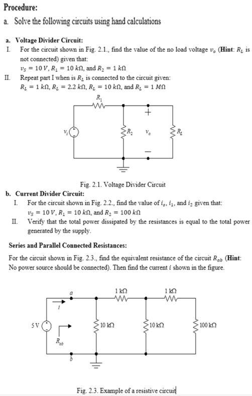
Procedure: a. Solve the following circuits using hand calculations a. Voltage Divider Circuit: I. For the circuit shown in Fig. 2.1., find the value of the no load voltage \( v_{0} \) (Hint: \( R_{L} \) is not connected) given that: \[ v_{S}=10 V V_{1}=10 \mathrm{k} \Omega \text {, and } R_{2}=1 \mathrm{k} \Omega \] II. Repeat part I when is \( R_{L} \) is connected to the circuit given: \( R_{L}=1 \mathrm{k} \Omega, R_{L}=2.2 \mathrm{k} \Omega, R_{L}=10 \mathrm{k} \Omega \), and \( R_{L}=1 \mathrm{M} \Omega \) Fig. 2.1. Voltage Divider Circuit b. Current Divider Circuit: I. For the circuit shown in Fig. 2.2., find the value of \( i_{z}, i_{1} \), and \( i_{2} \) given that: \[ v_{S}=10 \mathrm{~V}, R_{1}=10 \mathrm{k} \Omega \text {, and } R_{2}=100 \mathrm{k} \Omega \] II. Verify that the total power dissipated by the resistances is equal to the total power generated by the supply. Series and Parallel Connected Resistances: For the circuit shown in Fig. 2.3., find the equivalent resistance of the circuit \( R_{a b} \) (Hint: No power source should be connected). Then find the current \( i \) shown in the figure. Fig. 2.3. Example of a resistive circuid