Home /
Expert Answers /
Electrical Engineering /
procedures-part-2-rc-circuit-with-pulse-input-simulation-the-input-voltage-v-1-is-a-pulse-with-the-pa418
(Solved): Procedures Part 2: RC Circuit with Pulse Input Simulation The input voltage V 1 is a pulse with the ...
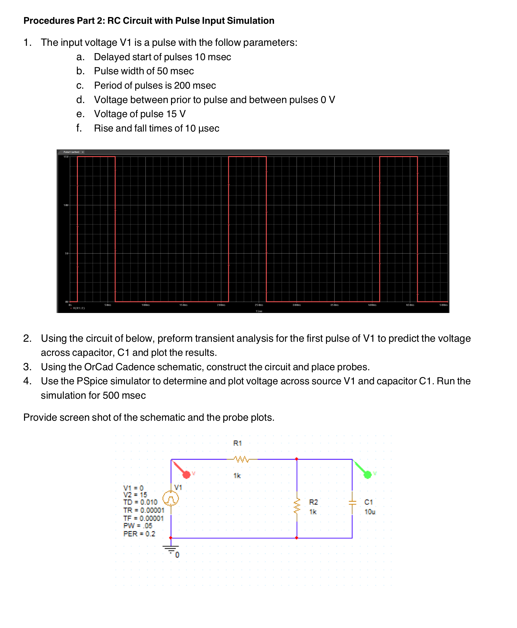
Procedures Part 2: RC Circuit with Pulse Input Simulation The input voltage
V1 is a pulse with the follow parameters: a. Delayed start of pulses
10msecb. Pulse width of
50msecc. Period of pulses is
200msecd. Voltage between prior to pulse and between pulses
0Ve. Voltage of pulse
15Vf. Rise and fall times of
10\mu secUsing the circuit of below, preform transient analysis for the first pulse of
V1to predict the voltage across capacitor, C1 and plot the results. Using the OrCad Cadence schematic, construct the circuit and place probes. Use the PSpice simulator to determine and plot voltage across source V1 and capacitor
C1. Run the simulation for
500msecProvide screen shot of the schematic and the probe plots.