Home /
Expert Answers /
Electrical Engineering /
question-1-11-points-create-the-circuit-shown-below-diode-equivalent-bjt-npn-transistor-a-d1-02-d-pa442
(Solved): Question 1 11 Points Create the circuit shown below Diode Equivalent BJT NPN Transistor A D1 02 D ...
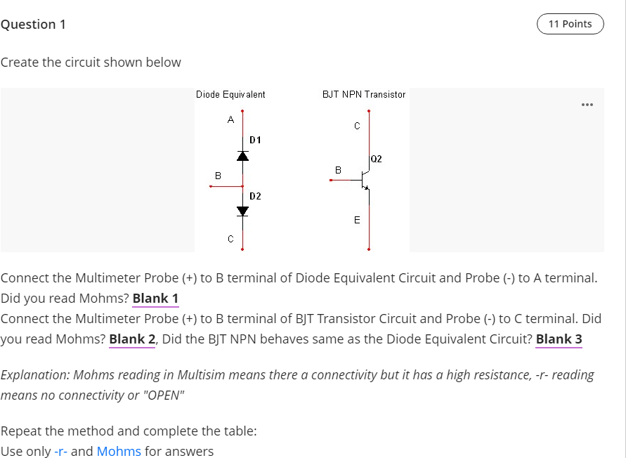

Question 1 11 Points Create the circuit shown below Diode Equivalent BJT NPN Transistor A D1 02 D2 E Connect the Multimeter Probe (+) to B terminal of Diode Equivalent Circuit and Probe (-) to A terminal. Did you read Mohms? Blank 1 Connect the Multimeter Probe (+) to B terminal of BJT Transistor Circuit and Probe (-) to C terminal. Did you read Mohms? Blank 2, Did the BJT NPN behaves same as the Diode Equivalent Circuit? Blank 3 Explanation: Mohms reading in Multisim means there a connectivity but it has a high resistance, -r- reading means no connectivity or "OPEN" Repeat the method and complete the table: Use only-r- and Mohms for answers
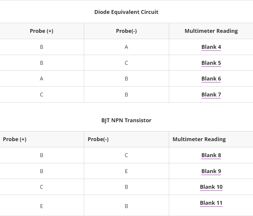
Diode Equivalent Circuit Probe (+) Probe(-) Multimeter Reading B ? Blank 4 B ? Blank 5 ? B Blank 6 ? B B Blank 7 BJT NPN Transistor Probe (+) Probe(-) Multimeter Reading B ? Blank 8 B B E Blank 9 C ? B B Blank 10 Blank 11 E B
Blank 1 Add your answer Blank 2 Add your answer Blank 3 Add your answer Blank 4 Add your answer Blank 5 Add your answer Blank 6 Add your answer Blank 7 Add your answer Blank 8 Add your answer Blank 9 Add your answer Blank 10 Add your answer Blank 11 Add your answer
Expert Answer
Created a circuit in Multisim as shown in Fig. No. 1. Fig No. 1 Using a Multimeter (Ohmmeter setting) a. Connect the multimeter Probe (+) to B terminal of Diode Equivalent Circuit and Probe (-) to A terminal. Screenshot Multimeter Reading. Solution: