Home /
Expert Answers /
Electrical Engineering /
question-1-a-lti-systems-has-the-block-diagram-as-shown-in-figure-1-1-draw-the-signal-flow-grap-pa869
(Solved): Question 1: A LTI systems has the block diagram as shown in Figure 1. 1. Draw the Signal Flow Grap ...
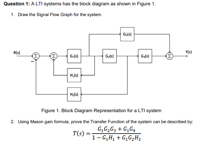
Question 1: A LTI systems has the block diagram as shown in Figure 1. 1. Draw the Signal Flow Graph for the system. G?(s) Y(s) R(s) (?) (? G?(s) G?(s) G3(S) ? H?(s) H?(s) Figure 1. Block Diagram Representation for a LTI system 2. Using Mason gain formula, prove the Transfer Function of the system can be described by: T(s) = G? G? G3 + G?G4 ¯1-G?H? + G?G?H?