(Solved): Question 6 (20 Marks) Figure Q6(a) shows a power MOSFET switched from a control circuit and driving ...
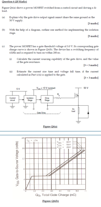
Question 6 (20 Marks) Figure Q6(a) shows a power MOSFET switched from a control circuit and driving a dc load. (a) Explain why the gate drive output signal cannot share the same ground as the 50 V supply. [3 manks] (b) With the help of a diagram, outline one method for implementing the isolation stage. [5 marks] (c) The power MOSFET has a gate threshold voltage of 3.0 V . Its corresponding gate charge curve is shown in Figure Q6(b). The device has a switching frequency of 4 kHz and is required to turn on within 200 ms . (a) Calculate the current sourcing capablaty of the gate drive, and the value of the gate resistance. [3+3 marks] (ii) Estimate the current rise time and voltage fall time, if the current calculated in Part (c)(D) is applied to the gate. \[ \text { [3 + } 3 \text { marks] } \]